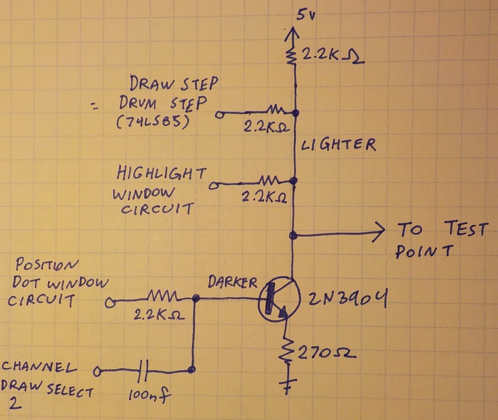
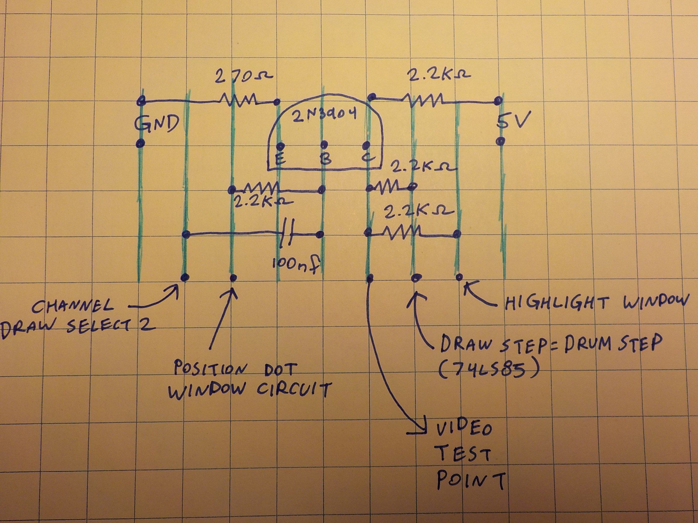
So far I've covered three circuits with outputs to the TV: The position dot window circuit; the highlighting window circuit; and the 74ls85 output that highlights the step the drum sequencer is presently on. I'm adding a fourth video output at this point: a set of sixteen dark lines that divide each step. With this dark line it's easier to differentiate the individual channels within each step.
The separator line is done by running channel draw select 2 through a capacitor. This creates an edge detector that responds to the transition it makes when the channel draw count resets.
The four signals are mixed with a simple transistor circuit. It produces a light grey by default. Inputs to the collector bump up the brightness. Inputs to the base bump down the brightness. The highlight and drum step indicator are drawn as white. The separator line and position dots are drawn as darker grey.
 Russell Kramer

Discussions
Become a Hackaday.io Member
Create an account to leave a comment. Already have an account? Log In.