 mircemk
This innovative technology eliminates the need for traditional power cables, offering a convenient and efficient way to charge or power various devices.
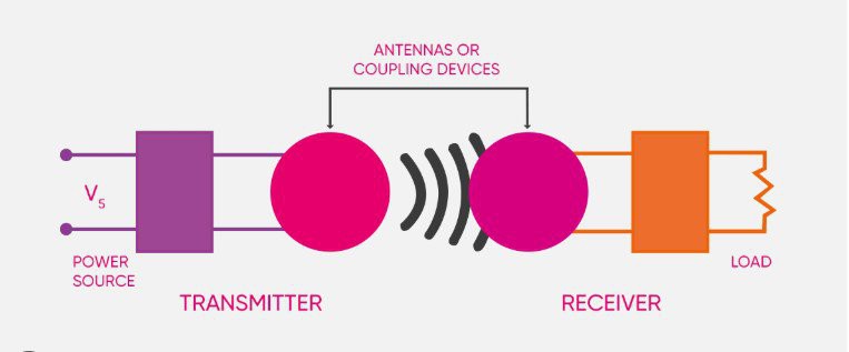
A wireless power transmission system generally consists of transmitter that converts input power into a time-varying electromagnetic field and receiver that receive the power from the electromagnetic field and convert it back into DC or AC electric current, which then powers an electrical load. In some of my previous videos, I presented a way to build such systems, one of which focused on the transmission distance, and the other on the coefficient of efficiency (i.e., transmitting more power over shorter distances). This time, I will present you with such an experiment that combines the positive aspects of the two previously mentioned projects.
Unlike previous projects, where I used a so-called Mazzilli ZVS driver on the transmitter side, this time I will use a modified Class-E Tesla coil circuit, where the no-load consumption is minimal and at the same time the transmitted energy over a given distance is relatively large. The device is really simple to make and consists of a minimal number of components.
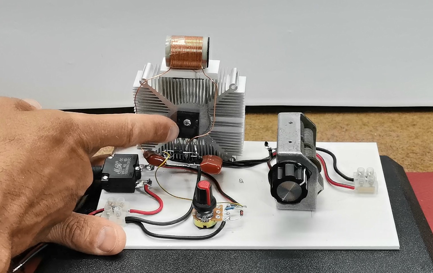
- IRFP260N Power Mosfet
- few resistors
- Potentiometer
- Zener diode and TVS protector
- two capacitors
- one coil consist 30 turns enammeled copper wire with 0.5mm cross section
- And Transmiting and receiver coils
I wound these coils on a plastic cylinder with a diameter of 11cm and used insulated wire with a thickness of 1.5mm.
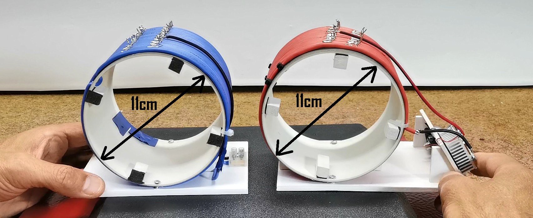
As you can see on these coils I made an output for each single turn so that I could precisely choose the optimal number of turns during experimentation. For the consumer on the receiving side I use a combination of a 10 watt LED and a regular white 10mm LED so that I can cover both aspects - the maximum transmission distance and the maximum power.

This project is sponsored by PCBWay. They has all the services you need to create your project at the best price, whether is a scool project, or complex professional project. On PCBWayyou can share your experiences, or get inspiration for your next project. They also provide completed Surface mount SMT PCB assemblY service at a best price, and ISO9001 quality control. Visit pcbway.com for more services.

This time I will not make precise measurements of the transmitted power because we are dealing with high frequencies during the transfer so you can visually roughly conclude about the amount of power and the distance. First, let me briefly explain the circuitdiagram:
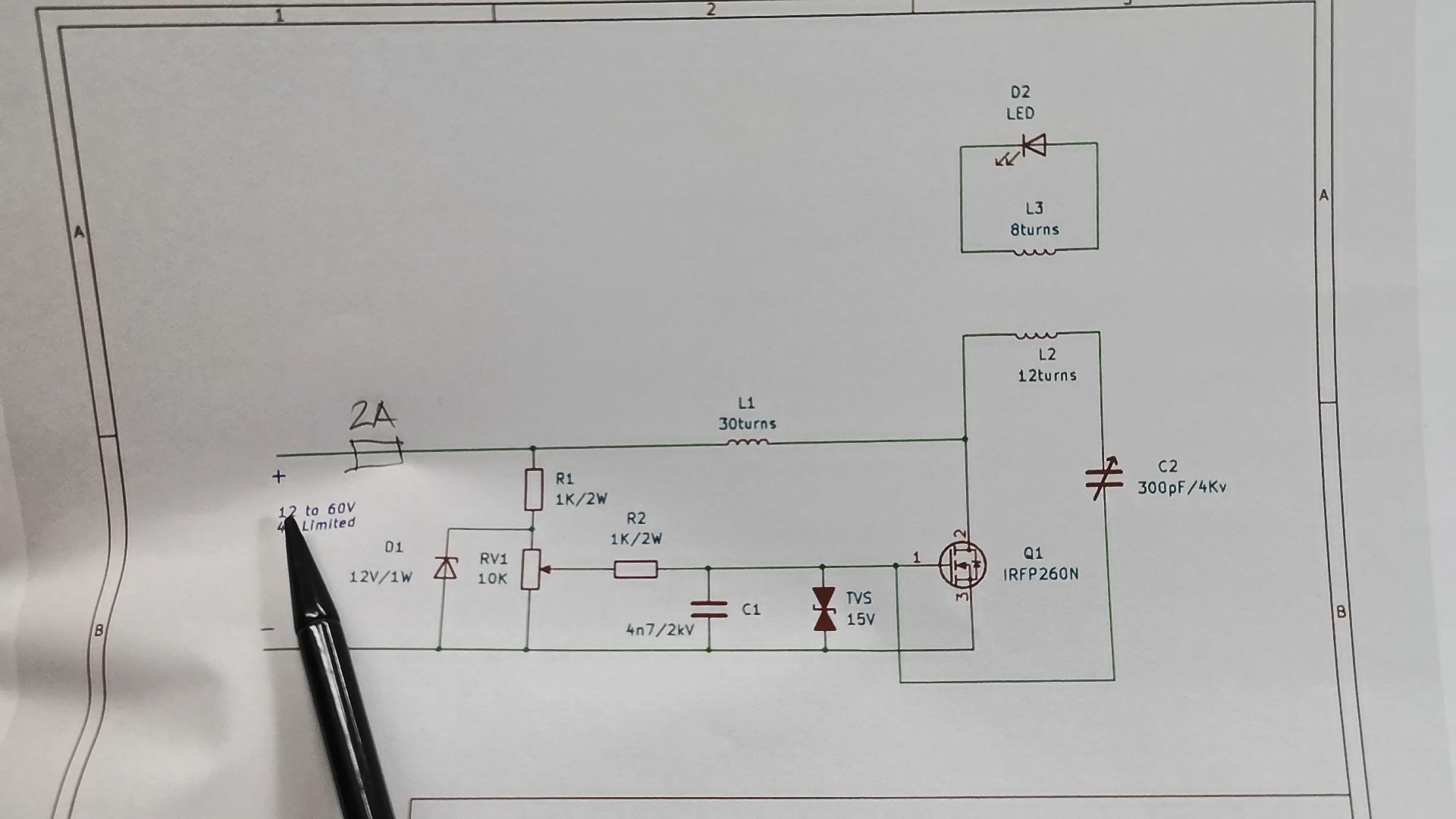
The device is powered by 9 to 60 volts DC and to protect the mosfet, the current at the source is limited to 2A. There is an automatic 2A fuse at the input to turn off the source in case of damage to any of the components. With the potentiometer, we adjust the voltage at the gate, and D1 and TVS serve to protect against parasitic voltage peaks. The oscillation frequency depends on the values of C2 and L2 and with these specific values is about 2 MHz.
For C2 I use a variable capacitor from an old Tube radio, with which I can change the oscillation frequency within a certain range.
Next comes the interesting part, which is testing. On the Power Supply display, we will monitor the voltage, current, and total power consumed on the transmitter side. Let me tell you that I determined the optimal number of turns on the transmitter and receiver coils experimentally after many hours of testing. The transmitter coil contains 12 turns, and the receiver coil contains 8 turns.
First, I will test at what greatest distance, while using the lowest possible consumption, I will be able to light a 10-watt LED. Let's see the total consumption of the device in idle mode, with a voltage of 12V.
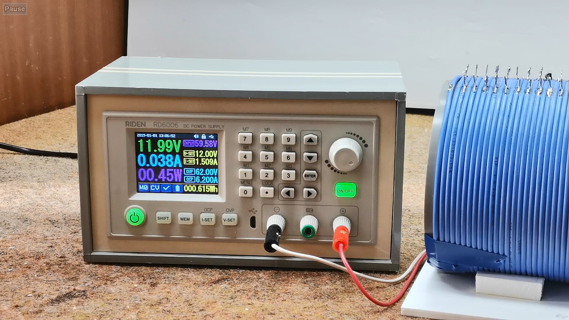
We see that it is less than 0.45 watts, and if you look at the previously mentioned video using the ZVS driver, it was about 71W, which is more than 150...
Read more »

 G. Rosa
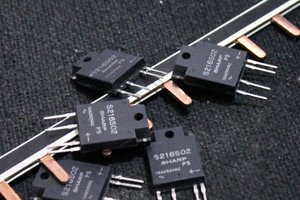
 Yann Guidon / YGDES