 Andy Geppert
Here is what I settled on for power into the SAOfinity system, composed of three parts (bring-your-own-USB C-power pack):
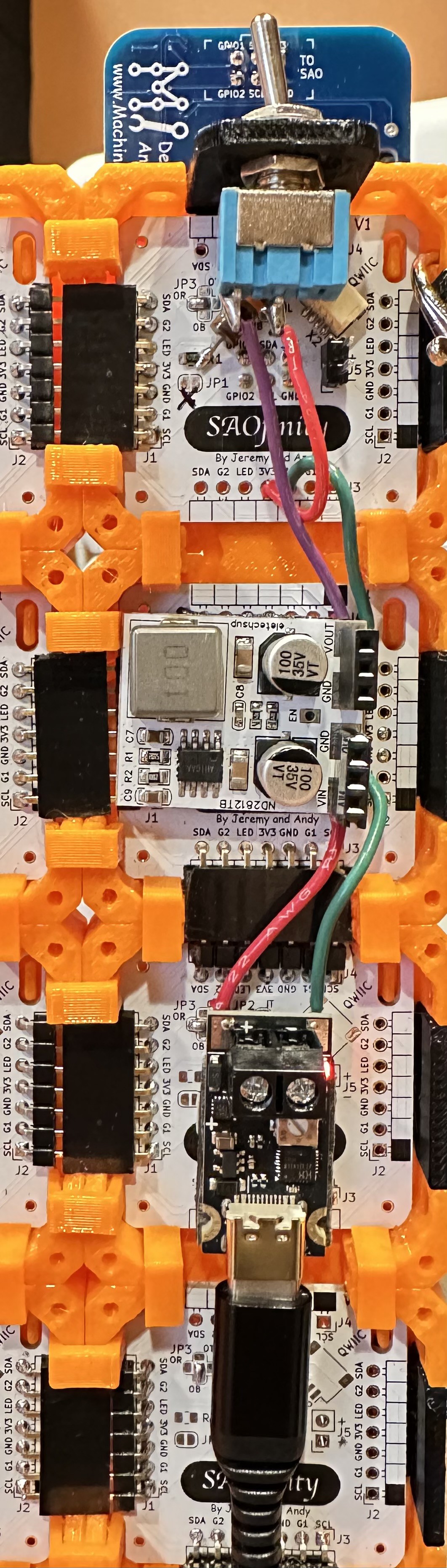
From the bottom, to the top:
(A) Input starts with a USB C PD board.
If you get a kit from us at Supercon, it'll be a slightly different that shown above.
https://www.amazon.com/dp/B0F8VTTXXT
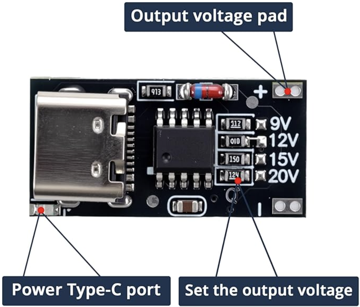
The ones I purchased have the output preset at 12V, but any of the output ranges should work fine with the voltage regulator below.
(B) Then to a voltage regulator board.
https://www.ebay.com/itm/285420629162
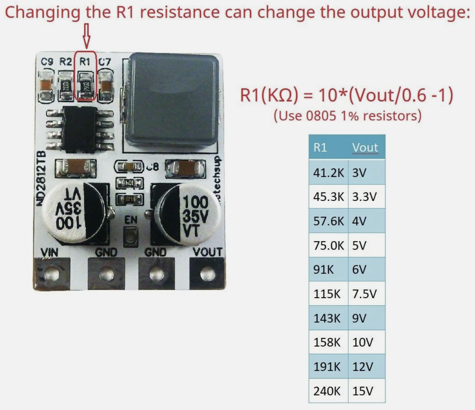
This claims to deliver 4 Amps from a 4.5 to 28VDC input, and with a resistor, you can order/change the output voltage to be in 3 to 12V. One of the pictures in the listing shows the resistor calculations. I ordered the 3.3V output version, and changed/included R1 to 51K Ohms, to get 3.66V for a little more headroom on the long power bus. It works well. Maybe ordering these preset to 4V is a better solution in the long-run, assuming all your SAOs can handle 4V.
(C) Finally through a power switch.
https://www.amazon.com/dp/B0799LBFNY

I had to add the power switch at the last minute because I discovered that the voltage regulator output ramps up [relatively] slowly and that causes some problems with the SAO Demo Controller and LEDs on the tiles. Without the switch, several of the RGB LEDs on the tiles would trip out and fail to operate correctly. I also attempted to mitigate that issue by putting a 10K Ohm resistor on the signal line on the back of the first SAOfinity PCB tile:
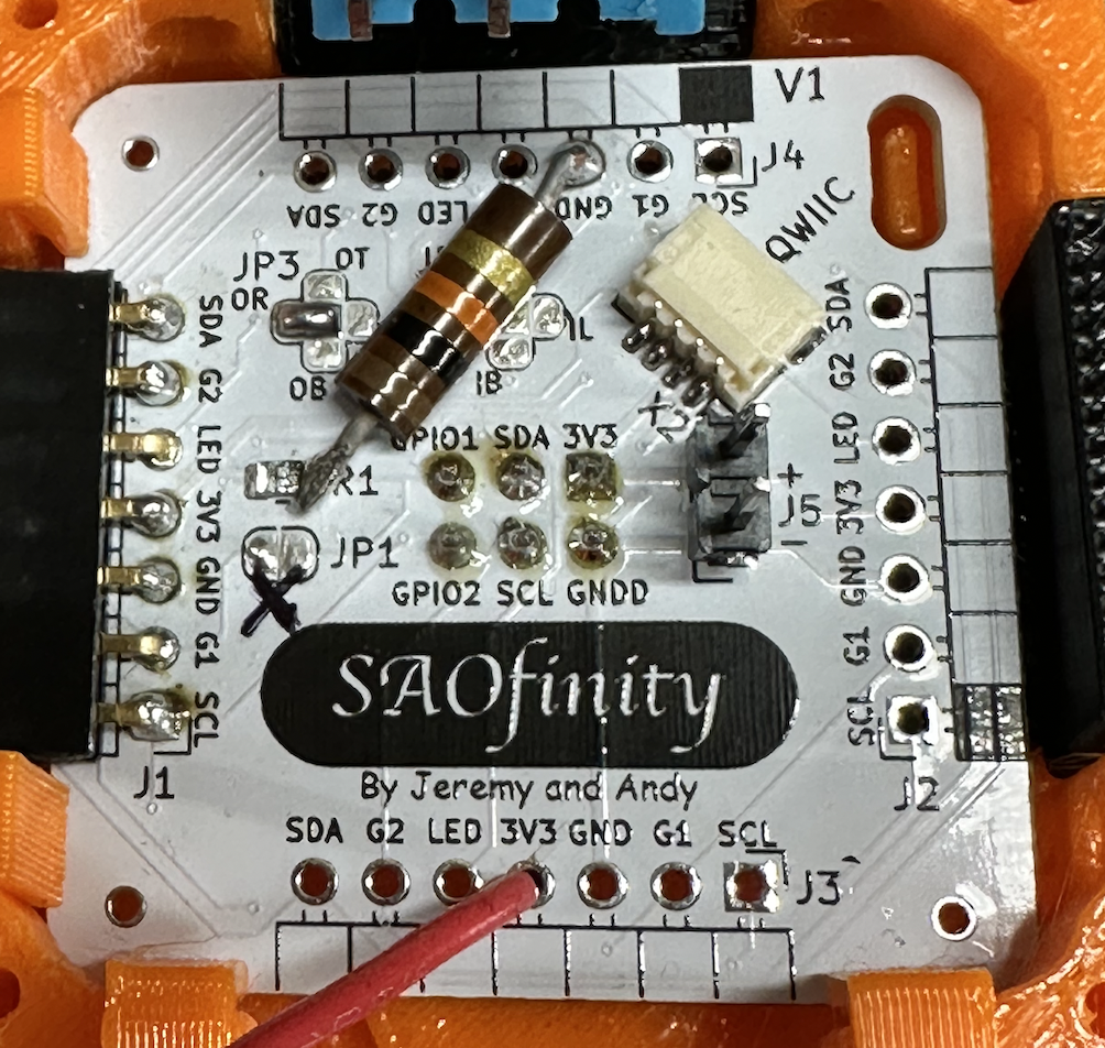
And the final final step is routing the switched 3V3 into one of the open 3V3 pins on the first tile. And ground to GND of course. On the PCB, all GND and 3V3 pads are connected together.
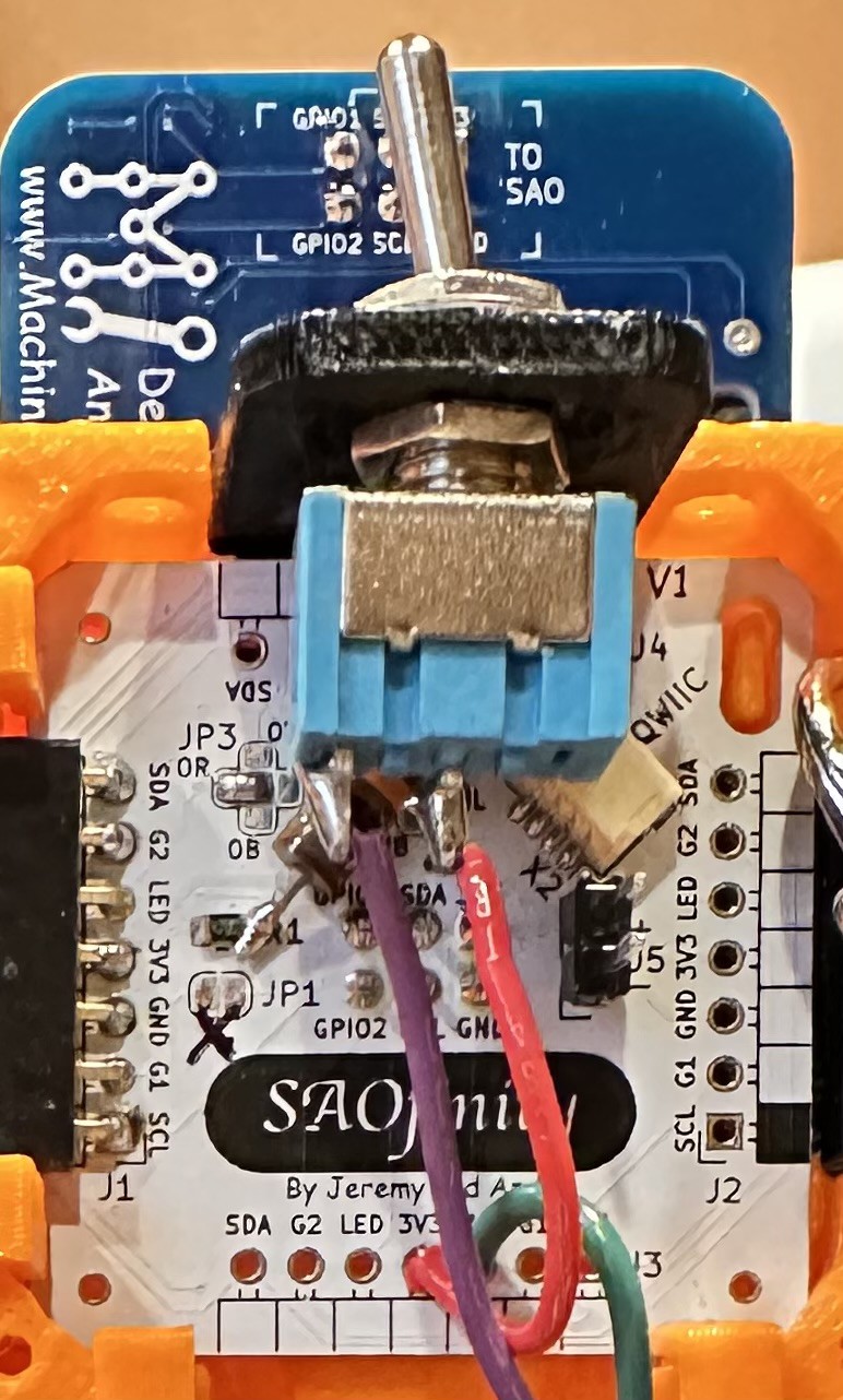
The power switch and SAO Demo Controller (not included - but available) are intended to operate from the first SAOfinitiy tile in the series, which is arbitrarily suggested as upper left, when viewed from the front. This has to do with the suggested signal routing for the built-in RGB LEDs.

The V1 kits include all of these components, wires, double-sided tape, switch, switch mounting bracket, resistors. And a USB C to C cable!
If all you need is power to the tiles, then you only need to connect the 3V3 and GND from tile to tile. The other connections are all optional. But each board does have a built-in RGB LED, so you'll probably want to connect the LED signal from board to board (in series only!). More on that in the next ASSEMBLE: LED Signal Chain blog entry.
Discussions
Become a Hackaday.io Member
Create an account to leave a comment. Already have an account? Log In.