 Tim
TimSo now we have a clock source of ~9.9 Hz and a way to extract a signal from it. First, let's marvel at the result! You can see the candle flickering at 10 Hz and the LED next to it blinking at 1 Hz! The framerate of the GIF is unfortunately limited, which causes some aliasing. You can see a higher framerate version on YouTube or the original file.
Let's take a quick look at how to put this all together to extract a 1 Hz clock, as desired for the challenge. All code for analysis and the microcontroller can be found in the GitHub repository.
I recorded data traces with a Python tool from the monitor output and used a separate script to analyze data and prototype the signal processing chain. The sample rate is limited to around ~90 Hz due to the overhead of printing data via the debug output, but the data rate turned out to be sufficient for this case.
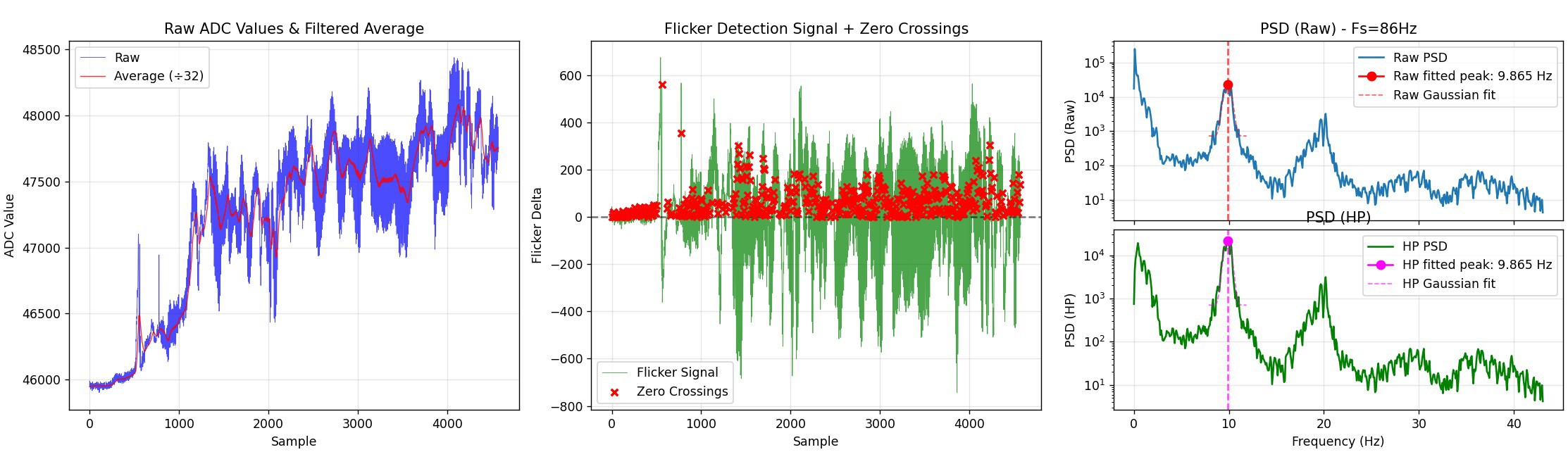
The image above shows an overview of the signal chain. The raw data (after 32x averaging) is shown on the left. The signal is filtered with an IIR filter to extract the baseline (red). The middle figure shows the signal with baseline removed and zero-cross detection. The zero-cross detector will tag the first sample after a negative-to-positive transition with a short dead-time to prevent it from latching to noise. The right plot shows the PSD of the overall and high-pass filtered signal, showing that despite the wandering input signal, we get a sharp ~9.9 Hz peak for the main frequency.
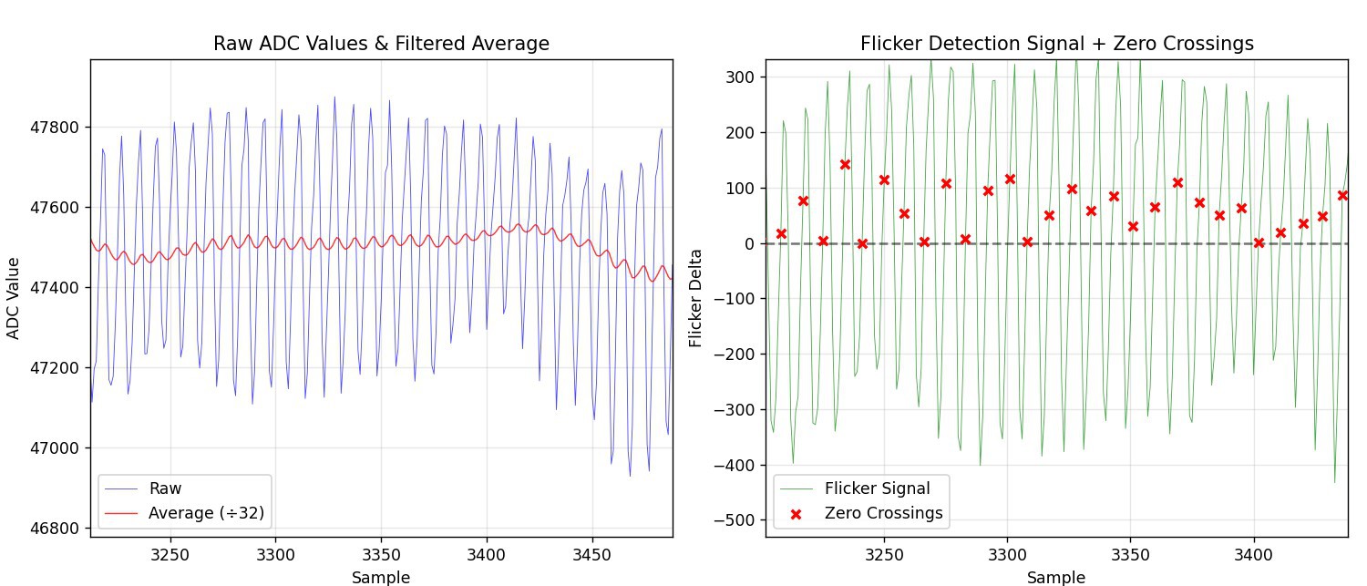
A detailed zoom-in of raw samples with baseline and HP filtered data is shown below.
The inner loop code is shown below. Implementation of IIR filter, HP filter, and zero-crossing detector are demonstrated. Conversion from 9.9 Hz to 1 Hz is implemented using a fractional counter. The output is used to blink the attached LED. This shows the concept nicely! An advanced implementation using a software-implemented DPLL might provide a bit more stability in case of excessive noise or missing zero crossings, but that's for later...
const int32_t led_toggle_threshold = 32768;  // Toggle LED every 32768 time units (0.5 second)
const int32_t interval = (int32_t)(65536 / 9.9); // 9.9Hz flicker rate
...

sum = ReadTouchPin( GPIOA, 2, 0, iterations );

if (avg == 0) { avg = sum;} // initialize avg on first run
avg = avg - (avg>>5) + sum; // IIR low-pass filter for baseline
hp = sum -  (avg>>5); // high-pass filter

// Zero crossing detector with dead time
if (dead_time_counter > 0) {
    dead_time_counter--;  // Count down dead time
    zero_cross = 0;  // No detection during dead time
} else {
    // Check for positive zero crossing (sign change)
    if ((hp_prev < 0 && hp >= 0)) {
        zero_cross = 1;
        dead_time_counter = 4;
        time_accumulator += interval;

        // LED blinking logic using time accumulator
        // Check if time accumulator has reached LED toggle threshold
        if (time_accumulator >= led_toggle_threshold) {
            time_accumulator = time_accumulator - led_toggle_threshold;  // Subtract threshold (no modulo)
            led_state = led_state ^ 1;  // Toggle LED state using XOR

            // Set or clear PC4 based on LED state
            if (led_state) {
                GPIOC->BSHR = 1<<4;  // Set PC4 high
            } else {
                GPIOC->BSHR = 1<<(16+4);  // Set PC4 low
            }
        }
    } else {
        zero_cross = 0;  // No zero crossing
    }
}

hp_prev = hp;
That's all for the journey from undoing millennia of candle-flicker-mitigation work to turning this into a clock source that can be sensed with a bare wire and a microcontroller.
Back to my decade-long quest to build a perfect electronic candle emulation...
Discussions
Become a Hackaday.io Member
Create an account to leave a comment. Already have an account? Log In.