 SonOfSofaman
I had learned about Linear Feedback Shift Registers (LFSR) as a means of generating sequences of numbers. An interesting property is their ability to generate numbers that do not repeat until every distinct value has been produced exactly once. Another interesting property is that the sequence of numbers appears to be random. The sequence isn't random at all, but the illusion of randomness is convincing. The term pseudorandom is used to describe this.
A key concept of an LFSR is it generates numbers one at a time. A new number is generated each time the LFSR is invoked, so you could get a new number on some regular time interval for example.
LFSRs work with binary representations of numbers. Every number is just a series of 1s and 0s. As a result, the range of values produced by an LFSR is always a power of 2, much in the same way that powers of 10 in our decimal numbering system are common.
One small detail: an LFSR will never generate a zero, so the length of the sequence is a power of 2, minus 1. If an LFSR ever produced a zero, it would get stuck producing a stream of zeros forever. Zeros are kryptonite to LFSRs.
When I heard about the One Hertz Challenge, I got the idea to use an LFSR to generate a sequence of pseudorandom numbers every second, however, I needed a way to display the numbers to an observer.
Neopixels are RGB LEDs capable of displaying 16,777,216 distinct colors. I thought it would be fun to express a series of distinct pseudorandom numbers as a pattern of pseudorandom colors of light. Since 16,777,216 is a power of 2, an LFSR is perfectly suited for the job.
All I needed was a 1 Hertz clock, an LFSR, and a Neopixel.
Here it is in action:
I did the math. 16,777,216 seconds is a long time. If my math is correct, that's 279,620.2666 minutes, or 4,660.33777 hours, or just over 194 days.
By the way, you could do all of this in software running on an Arduino, but, why would anyone want to do it the easy way?
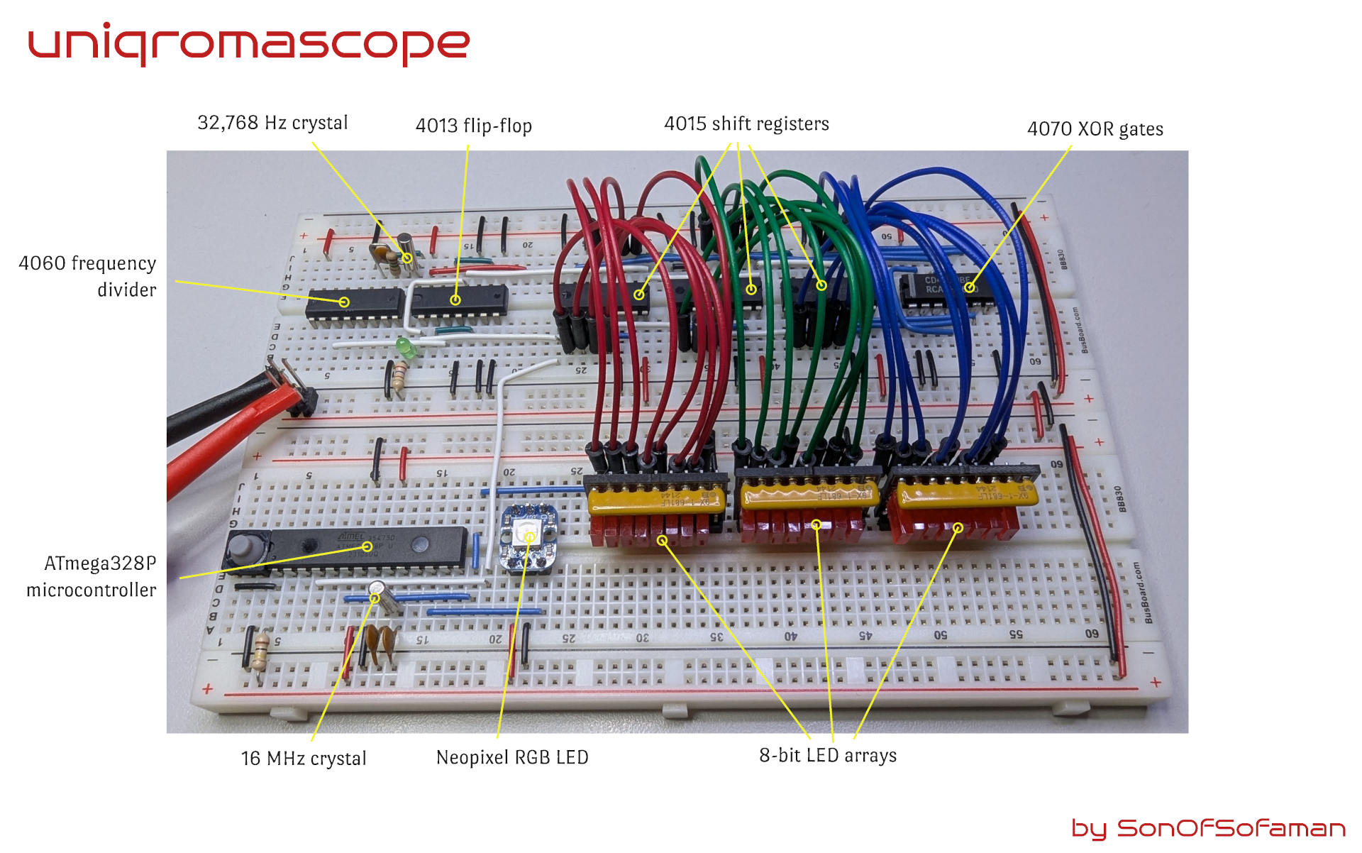
Here's a photo of the hardware:
The 1 Hertz Clock
The point of the challenge is to perform a task, once per second. In hardware, that means I need a clock. A clock is just a device that generates a pulse at a specific frequency.
Normally I'd turn to the good ol' 555 Timer for a job like this, but something with a cyclic period of over 194 days deserves to be precise. Besides, fake internet points are awarded for precision and I wanted an excuse to use crystals for the first time ... ever.
Crystal oscillators can be used to produce a steady, very precise pulse. They remain stable over a wide range of temperatures and are unaffected by ambient electromagnetic fields. By their nature, they vibrate at "high" frequencies, by that I mean higher than 1 Hz. For example, crystals that vibrate at 32,768 Hz are readily available; 1 Hz crystals do not exist (or they would have to be very, very, impractically large).
One way to produce a precise 1 Hz signal is to generate a precise 32,768 Hz signal, then divide that in half. Then in half again, and again and again 15 times.
32,768 = 2^15
2^15 ÷ 2^15 = 1
Dividing the frequency of a pulse is pretty easy using a cascading series of flip-flops. Flip-flops are basic building blocks of digital electronic circuits. The output of each floppy flipper is connected to the input of the next. A signal at the output of a flip-flop will pulse once for every two pulses at its input, effectively dividing the frequency by 2. Chain 15 of these together and the precise 32,768 Hz signal becomes a 1 Hz signal with no loss of precision.
Flip-flops exist as convenient integrated circuits, or "chips". For example, the 4013 is a CMOS IC that works perfectly for frequency division. But using them would require a lot of chips and a lot of wiring.
The 4060 IC contains 14 flip-flops already chained together. It also contains the oscillator circuitry that makes an external crystal do its magic. Attaching a 32,768 Hz crystal (and a capacitor and a resistor) to a 4060 gives you a very precise, very stable 2 Hz signal.
But I need a 1 Hz signal.
Adding one of those 4013 flip-flops mentioned above will divide the signal again to get the desired 1 Hz signal. And, since the 4013 has two flip-flops inside, you can even produce a 0.5 Hz signal for free if you want.
So, combining the 4060 with a 4013 gets the job done with 2 ICs instead of more than a half dozen ICs and you don't have to build your own oscillator around the crystal.
The Linear Feedback Shift Register
For me, this was the fun part. An LFSR works by taking a pattern of bits (1s and 0s), then shifting them one place. The last bit falls off, and that makes room for a new one at the beginning of the list. Think of books on a shelf. Push one and they all shift over. The last book falls off the shelf and leaves room for a new one.
It is important to capture the bit that fell off, and it is important to place a new bit in the empty space that opened up.
An LFSR computes the new bit by performing a simple logic operation on some of the other bits. Specifically, it takes bits 24, 23, 22 and 17 and performs an exclusive or (XOR) operation on them. Don't ask me why those four bits are special. The explanation used the word polynomial and that word causes my brain to reboot.
The XOR operation is kind of like adding some numbers together and throwing away everything but the last digit. In this case, the numbers are 1s and 0s of course so the remainder is always a 1 or a 0. The remainder is fed back into the empty space at the beginning of the pattern.
After shifting the bits and filling in the empty space with a new bit, you get a new pattern of bits. The new pattern is the next (pseudo) random number.
This cycle can continue forever. Each new pattern of bits is derived from the previous pattern in an endless cycle. And by some arcane mathamagic, no pattern of bits ever repeats until every possible pattern has been generated exactly once.
Shifting bits and performing XOR operations are trivial to implement using basic logic circuits. Since a LFSR is nothing more than shifting bits and an XOR feedback, making one with logic chips is really straightforward.
The 4015 is a CMOS IC that has two 4-bit shift registers which can be chained together to form an 8-bit shift register. Chain together 3 of these ICs and you have a 24-bit shift register. The bits are shifted whenever a pulse is received on the clock input.
The 4070 CMOS IC has 4 XOR gates on one chip. Only 3 are needed for a 24-bit LFSR. The inputs of the XOR gates combine the values of bits 24, 23, 22 and 17, and the output provides a new value for bit 1 when the bits shift.
XOR is a magical logic operation. Like other logic gates, the XOR has two inputs and one output. In the 24 bit LFSR, 4 inputs need to be combined into 1 output. There are at least two ways to do that: arrange 3 XOR gates as a ladder or as a tree. The arrangement used does not matter: they both produce the same results, either that or my truth table skills are faulty and I chose the correct arrangement by pure luck.
The Neopixel
A Neopixel can display over 16 million distinct colors. It does this by splitting the color into three channels: red, green and blue, then mixing the results. It's like mixing primary pigments in art class back in elementary school, but with light.
The brightness of each color can be controlled independently. Bright red + medium green + no blue produces orange light. Fully bright blue + medium red + no green makes a lovely shade of violet.
Using different amounts of the primary colors of light produces different results, just like mixing paint.
The Neopixel contains a small microchip. The microchip controls the brightness of each of the three color channels using a technique called pulse-width modulation (PWM).
What is pulse-width modulation?
Think of a lamp that you can turn on and off with a switch. If you cycle the light on and off, on and off, on and off, over and over again so that it is on half the time, and off half the time, the lamp will produce 50% of the light that it is capable of producing.
Now, do that fast. Really fast. Like 1000s of times every second.
Your eyes blur the on and off time together, and the result is the light appears to be half as bright. So if you can flip the light switch fast enough, you can control the brightness of the lamp.
Don't actually do that though, you'll probably damage the switch. Or the lamp. Or your fingers.
If you could flip the switch fast enough, and do it such that the light is on 25% of the time, and off the other 75%, you eyes will interpret the light at 1/4 brightness. A mix of 10% on 90% off produces 1/10 brightness and so on.
This is called pulse width modulation. A series of pulses (ons and offs) is sent to the lamp (or LEDs). The width of that pulse, the time spent on versus the time spent off, is varied to produce the desired brightness.
The microchip in the Neopixel does all this work. To use it, you just need to send it the desired mix of brightness for each of the red, green and blue channels expressed as three numbers from 0 (complete darkness) to 255 (full brightness). In binary, that's 00000000 (zero) and 11111111 (255).
Here's the math:
256 levels of red x 256 levels of green x 256 levels of blue = 16,777,216 distinct colors
Or, if you prefer exponential notation, 2^8 x 2^8 x 2^8 = 2^24 = 16,777,216
So how does the Uniqromascope send three brightness levels to the microchip in the Neopixel?
Recall the book analogy. One bit fell off the end when the pattern shifted. That bit is captured by an ATmega328P microcontroller.
The microcontroller
An LFSR generates a changing pattern of bits, 24 bits in the case of Uniqromascope. Every time that pattern changes, information needs to be sent to the Neopixel instructing it to show a new color of light.
There are two problems that need to be solved.
The first problem is the Neopixel needs a signal formed very precisely. A signal is just a voltage rising and falling over time. In the case of the Neopixel, the rising and falling voltage needs to happen according to a strict set of rules. That set of rules, or protocol, is known by the very imaginative name WS2811. There are variations of the protocol with equally clever names like WS2812 and WS2813 but the differences and the details are out of scope here. Leave a comment if you'd like to know more, it's actually very fascinating stuff despite the lackluster monikers. I digress.
I very much wanted to generate the WS28xx signal using only hardware. It turns out that is difficult to do in the few weeks I knew about the One Hertz Challenge. I still want to make it happen, but for now, I cheated and I used a software solution.
The ATmega328P microcontroller is a readily available device with a strong ecosystem of development tools and is commonly known as an Arduino.
Herein lies the second of two problems that needed to be solved. ATmega328P microcontrollers can accept inputs via its general purpose input/output (GPIO) pins. The LFSR is a 24-bit device. It generates patterns of bits 24 at a time. The microcontroller doesn't have that many inputs.
This is a common problem and it has a common solution. Instead of trying to read all 24 bits at once, read one bit at a time. After reading 24 consecutive bits, the entire pattern can be reconstructed in the microcontroller's memory.
Remember that bit that fell off the end when we shifted the pattern? That's the sole bit that gets captured by the microcontroller.
Every time the pattern of bits shifts, that discard bit gets routed to the microcontroller. There is a literal wire that connects the shift register to an input pin on the microcontroller.
Once the pattern is reconstructed in the microcontroller's memory, it can generate the proper signal according to the WS28xx protocol and send it to the Neopixel. The Neopixel interprets the signal and produces the desired color of light.
All of the above happens every time the clock pulses, once every second, forever.
Caveats, minutiae, disclaimers and lies
I cannot promise this thing actually works correctly. I could watch the Neopixel for 6 months straight, but I don't think my eyes are sensitive enough to discern 16 million distinct colors. Also, that thing is really bright. I'm still seeing spots.
I considered hooking the Uniqromascope up to a logging system and record every new pattern it generates. Then, after 6 months, I could check the results to ensure no pattern was generated more than once. I might still do that. Until then, I gave it my best effort. If you find a flaw, please tell me.
As I mentioned, the Neopixel is really bright. In the video you can see I stacked a few pill bottle caps over the Neopixel to diffuse the light a bit. Without the diffuser, the camera didn't really capture the colors accurately. I think it was automatically adjusting the exposure every time the color changed. I'll record another video with my DSLR which lets me manually control the aperture.
I am confident the clock oscillates very precisely at 1 Hz, at least to the precision my oscilloscope is capable of measuring.

The LFSR visualization uses only red LEDs, but they represent red, green and blue color channels. That feels like a missed opportunity if ever there was one! This is almost as big an oversight as the guy who coined the term "palindrome". What was he thinking? I have green and blue LEDs, I just need to assemble the arrays. By the way, those LED arrays are another project of mine that you can find it on my Github. If you do a lot of breadboarding and you find yourself using groups of 8 LEDs often, and you're tired of wiring up 8 current limiting resistors and trying to cram all of that into limited space, give these arrays a try. They take up only 9 tie points on the breadboard by utilizing vertical space instead of horizontal space. They are like bunkbeds.
Neopixels are individually addressable. That means you can string a bunch of them together with simple wiring and control each one independently. They are a little power hungry so an appropriate power supply would be needed. A string of many Neopixels can all change color in unison, or each could show a color different from the others. By changing the colors over time, animations can be constructed. They are very versatile. I didn't take advantage of those capabilities in this project but doing so would be trivial.
I told a lie. I'm not capturing the bit that falls off the end of the pattern. I'm capturing the new bit that gets generated by the XOR gates.
The point of Uniqromascope is to show a different color every second. If you watch the video and look at the photos, you'll see the Neopixel do just that, but you'll also see 24 LEDs next to the Neopixel that blink on and off. They kinda steal the show, actually.
For debugging and troubleshooting purposes, it was handy to be able to visualize the 24 bit pattern. I wanted to make sure the bits shifted the way they are supposed to.
Those 24 LEDs were intended only as a tool while developing the project and I intended to remove them once everything was working. All those LEDs blinking on and off is kinda cool though, so I didn't remove them.
Due to the cyclic nature of the process, I could technically capture any one of the 24 bits. The only thing that would change is synchronization between the LED arrays and the Neopixel. If I picked a bit near the middle, the Neopixel would lag behind the pattern visualization by about 12 seconds. If I took the last bit (the one that falls off), the lag would be 24 seconds. Since I left the LED display in the project, and you can see them right next to the Neopixel, the synchronization would be evident to the keen observer. That's why I'm using the new bit instead of the discarded bit.
So I lied about which bit I am using. But I wasn't lying about polynomials. Those things hurt.