Close
0%
0%

The Watch Tower

A transmitter that broadcasts the time at 1 bit-per-second to radio-controlled clocks

Similar projects worth following

There are some beautiful radio-controlled watches available these days from Citizen, Seiko, Junghans, and even Casio. These timepieces don’t need fiddling every other month, which is great if you have more than one or two and can never remember what comes after “thirty days hath September…”

In the US, these watches work by receiving a 60-bit 1-Hz signal on a 60-kHz carrier wave broadcast from Fort Collins, Colorado called WWVB. The broadcast is quite strong and generally covers the entire continental US, but some areas of the country can have unreliable reception. I live in the SF Bay Area in an area with high RF noise and my reception can be spotty. My watches sync often enough that it’s not an issue 363 days out of the year, but sometimes they can miss DST shifts for a day or two. The east coast is known to be even more challenging. And people who live in other countries such as Australia have generally been out of luck.

Wouldn’t it be great if anyone anywhere in the world could set up a home transmitter to broadcast the time so their watches were always in sync?

WWVB has been around awhile and there have been various other projects (1,2) that have demonstrated the feasibility of making your own WWVB transmitter. But these all had very limited range. I wanted to build something that could cover my whole watch stand and be based on a more familiar toolset for the typical hobbyist, namely USB-based 32-bit microcontroller development boards, WiFi, and Arduino. My goal was to make something approachable, reliable, and attractive enough it could sit with my watch collection.

Is this legal?

The FCC requires a license to transmit, but has an exemption for 60 kHz transmitters as long as the field strength is under 40 μV/m at 300 meters. You will definitely not exceed this limit 💪🏼

About WWVB

The classic WWVB transmits one bit of information per second (1Hz) and takes one minute (60 bits) to transmit a full time and date frame.

An example

Here’s an example of one 60 second time encoding (graphic designed for "light mode"):

image.png

You can see that the minute of the time is encoded in the first 10 seconds of the window. The hour is in the next 10 seconds, the day is between seconds 22 and 33, etc.

If we wanted to indicate that the time was 30 minutes past the hour, for example, we would set bits 2 and 3 (20 and 10) to “high”.


Bit00010203040506070809
Value4020108421
Example: 300110000

Similarly, the 7th hour of the day would be 0000111 for bits 12 thru 18.

It’s a trit, not a bit.

How do we represent “high” and “low” for each 1s bit? You might think it would just be a high voltage for high and a low voltage for low, like you would use on a digital arduino pin, but that’s not how it’s done.

WWVB “bits” are actually not just 0 and 1. They’re actually "trits” because they can represent a 0, 1, or a “mark”, and this is one reason why we can’t just use a simple high/low to represent them. The mark is important to allow simple receivers to orient themselves within the signal window. Your watch knows that the last second in the window and the first in the next window are both “marks”, and so it knows to start a new window whenever it sees two marks in a row.

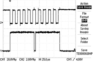
WWVB uses Pulse Width Modulation (PWM) to represent the three possible trit states. In a given 1 second bit, the width of the pulse determines whether the bit is a 0, 1, or mark.

  • If power is reduced for one-fifth of a second (0.2 s), this is a data bit with value zero.
  • If power is reduced for one-half of a second (0.5 s), this is a data bit with value one.
  • If power is reduced for four-fifths of a second (0.8 s), this is a special non-data "mark", used for framing.


LowTrit value
0.2s0
0.5s1
0.8smark

Coming back to that original example but just focusing on the Minutes section, you can see the trits in the color...

Read more »

  • 1 × Adafruit QT Py ESP32 An ESP32-based development board such as the AdaFruit QT Py ESP32, AdaFruit Feather ESP32 v2, Arduino Nano ESP32, Seeed Xiao ESP32C3 or similar. I used the QT Py ESP32.
  • 1 × Adafruit DRV8833 DC/Stepper Motor Driver Breakout Board An H-bridge amplifier circuit. You can build your own, or I used the Adafruit DRV8833 DC/Stepper Motor Driver Breakout Board. Boards using the TB6612 would probably also work, you just need something that can handle 5V or more, a few hundred milliamps and a switching frequency of 60khz or higher.
  • 1 × 60kHz ferrite rod antenna A 60khz ferrite rod antenna. You can pull one from an existing quartz radio-controlled movement, or I bought mine from Canaduino. If you want better reliability at distance you may consider using a second antenna. Some users have had luck with a simple 20 inch length of straight copper wire, but I found the signal to be too weak to be reliable.
  • 1 × Bread board and jumper wires
  • 1 × PCB Mount Screw Terminal Block connector PCB Mount Screw Terminal Block connector to connect your antenna, something like this. Not strictly necessary but nice to have. Use a two pin terminal if you only plan to have one antenna, or a four pin if you might use two antennas.

  • 1
    Instructions

    Simulator

    Before you get started, you might be interested to see a simplified version of the software in action on the Wokwi Arduino online simulator.

    The Watch Tower on Wokwi https://wokwi.com/projects/431240334467357697

    This simulator connects a virtual Arduino to a virtual logic analyser on PIN 4, and lets you download the output of PIN 4 for offline viewing on your computer.

    To use it:

    • Run the simulator for a few seconds. Notice that D0 is flashing on the logic analyzer. The logs will also show the current date/time (which starts at Jan 1 1970 since we aren't using wifi to initialize it to another value)
    • Stop the simulator. The logic analyzer will automatically download wokwi-logic.vcd to your computer.
    • Open wokwi-logic.vcd in a viewer like PulseView

    Software

    https://github.com/emmby/WatchTower

    Upload the Arduino sketch to your Arduino using the Arduino IDE.

    The LED will light up yellow/orange while connecting to WiFi. If you haven’t yet set your SSID, connect your phone to SSID: WWVB and follow the instructions to enter your wifi password.

    Once the network is connected and the time has sync’d, the light will turn green briefly and then turn off.

    Setup()

    The Arduino setup() method does a few things.

    Initialize the components we’ll be using, particularly the serial port, LEDs, WiFi, output pins, timezone, and network time sync (NTP). The network time sync will happen automatically in the background every hour. This is important because the realtime clock (RTC) on most microcontrollers are notoriously subject to drift and are rarely accurate for more than a few hours.

    Start the 60 kHz carrier wave at a 50% duty cycle.

    Loop()

    Arduino then moves to the loop(), which continuously performs the following operations:

    • Get the current time in UTC
    • Convert it to your local timezone to determine DST
    • Compute whether the 60 kHz carrier wave should be set to 50% (logical high) or 0% (logical low) for that specific moment in time. Time is always UTC, except for the DST bit which is relative to your local timezone.
    • Set the PIN_ANTENNA to high or low based on that value.
    • [Optional] you can flash the led for high/low PWM. This is nice for making sure things are working, but it’s grounds for divorce in the bedroom.

    Do some other nice-to-haves like logging, setting LEDs and/or rebooting when there are issues.

    Verify the microcontroller alone

    If you installed and ran your software and you set up the wifi connection, your board should now be outputting a signal on your output pin.

    If you have an LED, you can connect the long end (anode) to your output pin and the other end to ground. If everything is working it should flash on/off about once a second.

    ezgif-814d4a585a4921.gif

    If you have a digital oscilloscope, you should be able to see a 3V square wave with a periodicity of 16us (1 / 60,000) something like the following:

    RigolDS2.png

    That’s the 50% duty cycle PWM carrier wave initialized during setup().

    If you zoom out to say 1 second per grid square resolution, you’ll be able to see the WWVB signal clearly:

    RigolDS10.png

    In the 10 seconds shown here, I see a 1, mark, 0, 1, 1, mark, 1, 1, 1, and 1.

    Now if you modify the software to hardcode the date to Mar 6, 2008 7:30:00 am and zoom out to see a full 60 seconds, your signal should exactly match the signal in the example we started with:

      buf_now_utc.tm_year = buf_now_local.tm_year = 108; // 2008 = 1900 + 108  buf_now_utc.tm_yday = buf_now_local.tm_yday = 65;  buf_now_utc.tm_mon = buf_now_local.tm_mon = 2;  buf_now_utc.tm_mday = buf_now_local.tm_mday = 6;  buf_now_utc.tm_hour = buf_now_local.tm_hour = 7;  buf_now_utc.tm_min = buf_now_local.tm_min = 30;

    image.png

    image.png

    Looks great! Everything is working as expected.

    Electronics assembly

    Now that you’ve verified the microcontroller is working, it’s time to put all the components together.

    The electronics consist of three basic components: the microcontroller board, the amplifier breakout board, and the antenna.

    The connections are quite simple, you can do them on a breadboard or a proto board. I recommend starting with a breadboard, which will look identical to this perma-proto board but without the solder:

    Microcontroller board (Adafruit ESP32 QT Py in this photo)

    • Connect the 5V pin to the power plane (photo: J1).
    • Connect the ground pin to the ground plane (photo: J2).
    • Connect your signal pin [M0] to the input pin of your amplifier [AIN1] (photo: J4>J15).

    DRV8833 Amplifier breakout

    I decided to leave a gap between my microcontroller board and my amplifier board. This will support an optional second antenna mounted vertically (you'll read more about this later), and it also makes it easier to access the STEMMA QT I2c connector on the QT Py.

    • Connect the second input pin [AIN2] of your amplifier to ground (photo: J16).
    • The Adafruit DRV8833 motor driver board has a sleep pin that needs to be pulled high to enable the breakout, so connect that to power 5v or 3v power, whatever is convenient. We used 5V here. (photo: J17)
    • Connect ground to the ground plane. (photo: J21)
    • [Optional] Connect the “motor” voltage [VM] to your 5V plane (photo: J22). This is needed if you are powering your amplifier via USB like I have here, but it should not be done if you are planning to use an external power supply on VMotor. The antenna and amplifier circuit can contribute some noise to your 5V line. If you’re worried about it you might use an external power supply instead, but I found for these settings that the noise was negligible (although see Alternatives Considered for some lessons learned).
    • Optional: connect BIN2 to ground (photo: J18). This is only needed if you want to use a second antenna.
    • Optional: connect BIN1 to AIN1 (not in photo: I15>I19). For a second antenna.

    Antenna

    • You can plug your antenna directly into your breadboard, or use a 0.1" Pitch PCB Mount Screw Terminal Block Connector connected to [AOUT1], [AOUT2], [BOUT2], and [BOUT1] (photo: C16, C17, C18, C19). If you are only using one antenna, you only need [AOUT1] and [AOUT2].

    Signal Verification

    You should be able to do the same LED trick as last time, only this time with the long anode on AOUT1 and the short cathode on AOUT2.

    Or with your oscilloscope, you can look at the output of your microcontroller and compare it to the output of your amplifier:

    RigolDS6.png

    Here the 3V signal on the microcontroller is blue, and you can see that the amplifier is outputting a similar wave but at 5V. If your wave doesn’t look quite like this, check that your antenna is plugged in. The antenna has an impedance that will cause the ringing that you see in the waveform, that’s expected and okay.

    The final test is to verify it works with a real watch!

    ezgif-21153c1710707a.gif

    Assembling the enclosure

    The enclosure is designed for a 51mm x 63mm perma-proto, which is the size of a half size perma-proto with the excess trimmed. You can trim a proto board by scoring along a straightedge with a utility knife and then bending the board at the score, either by pressing it down on a hard surface at an angle or using a vise grip. Or feel free to modify the Autodesk Fusion file to the size of your own board.

    image.png

    Here I also made a quick and dirty “mount” for the antenna by twisting a couple of loops of wire and soldering them to the perma proto.

    Print the enclosure using a 3D printer. I used standard PLA, standard 0.4mm nozzle, and pretty much default slicer settings with no supports.

    image.png

    Insert the circuit board into the base. Then press the lid for a snap fit.

    Enjoy!

    Plug into USB and you’re done! Your watches should now sync automatically every night.

    image.png

    I get about 8 to 10 inches of signal in a straight line with no obstructions for watches. With a bedside clock like the Hito C8376, I get 3 or 4 feet due to its larger antenna.

    If you need more than that, I recommend adding a second antenna at a 90 degree orientation from the first. You won't get a more powerful signal, but by having a second signal at a 90 degree orientiation you significanly increase the chance that your watches will be able to pick up a signal (see the section on antenna orientation below). The amplifier can easily handle two antennas.

    If you soldered the optional [BOUT1] and [BOUT2] on your amplifier, you can plug your second antenna in there. If not, you can plug both antennas into [AOUT1] and [AOUT2], the single H-bridge has enough power to drive both antennas.

    The STL tower has a hole in the center to allow space for a 60mm ferrite rod antenna mounted vertically in the gap between the microcontroller and amplifier PCBs.

    If you still need more power, try giving a higher voltage a try using an external power supply to your amplifier.

    Signal strength

    How does distance affect signal strength?

    You probably expect the signal to decrease as you get further away from the tower, but you might be surprised by how quickly the signal disappears.

    The "inverse square law" tells us that RF signal strength decreases with the square of the distance. We can measure our signal strength using our oscilloscope, another antenna, and a ruler.

    signal strength at 1 inch setup

    At one inch, our signal strength looks pretty solid! You can see that our 5V antenna square wave (yellow) is inducing a 16V sinusoidal wave in our receiving antenna. It's a little counter-intuitive that the receiving amplitude would be larger than the sending amplitude, but RF physics is beyond the scope of this README. Which is another way of saying 🤷.

    signal strength at 1 inch

    Here are my readings as I move the receiver antenna further out. As expected, the amplitude decreases by roughly 4X as the distance doubles.

    DistanceAmplitude
    1"24.2V
    2"6.7V
    4"1.2V
    8"301mV
    16"93mV
    32"28mV

    When you zoom out, the one second pulses are still clearly distinguishable to the human eye, but it gets harder and harder as you get further away.

    alt text

    This is all fine and good, but seeing a wave on an oscilloscope doesn't necessarily mean the watch can pick it up. We'll get into that shortly.

    How does orientation affect signal strength?

    Quite a lot!

    Turning the receiver antenna 90 degrees drops the signal by 75%!

    rotation

    Most watches receive their strongest signal through the watch face. For the best reception you should point your watch toward the tower (or toward Colorado). This may make more of a difference than a few inches of distance.

    This doesn't matter for watches on the stand where the signal is strong, but it can make a difference for watches that are further away.

    Does the enclosure affect signal strength?

    Plastic enclosures have a negligible effect on signal strength. The Watch Tower enclosure printed using generic PLA has maybe 5% or less of an impact on signal strength. Again, a few degrees of orientation will have a larger effect than an enclosure.

    No enclosure1.02V
    Base952mV
    Fully enclosed987mV

    How far away can my watch pick up the signal?

    Watches vary in terms of their antenna design, their enclosures, antenna orientation, signal-to-noise filtering, etc.

    I tested with a Junghans Max Bill Mega Solar 59/2021.02 (Seiko movement) and a Casio Lineage LIW-M700D (Casio movement). In practice, the orientation of your watch will probably have orders of magnitude more influence on your reception than the model of your watch.

    I made five attempts with each watch at a distance of 9" with the antenna and the watch both flat on the surface. To minimize interference from Fort Collins, I placed everything inside a poor man's faraday cage (a stainless steel stock pot with a tight lid, which Gemini tells me is reasonably effective at blocking 60 kHz signals). For each attempt, I gave the watch 5 minutes to try to set the time before I lifted the lid.

    clock in a pot

    Model
    CasioYesNoYesYesYes
    JunghansYesYesYesYesYes

    Outcome: ~90% success at 9"

    In practice, I've found that watches on the Watch Tower will reliably sync every time, and most watches on my nearby watch stand will also sync most of the time. As a next step I may consider adding more towers to the Watch Tower to bring my whole collection closer to the antenna.

    Alternatives considered

    • I wanted to avoid using a separate amplifier breakout board so I tried the Adafruit RP2040 scorpio. It can do 60khz PWM at 5V natively, but it was only able to drive 12mA per channel which wasn’t enough to saturate my ferrite antenna so the square wave collapsed.
    • I looked at the Adafruit 8-Channel PWM or Servo FeatherWing because I wanted to take advantage of module stacking, but it can only do 10mA per channel and 1.6khz.
    • I looked at Trinket and Itsybitsy ATmega based boards, but they can’t drive much current and they’re not modular with anything and they have no wifi so there’s little advantage over the QT Py.
    • I considered driving the DRV8833 with an external power supply. This would have given me higher voltage and likely a stronger signal. But I wanted the convenience of a single usb power supply, and the signal strength was sufficient for my needs.
    • ⚠️ WARNING: I tried the linking both the A and B H-bridges of the DRV8833 in parallel, and I also upped the duty cycle to 80%. Totally blew out my microcontroller, presumably with a flyback voltage due to the high inductance antenna. I’m not sure if it was the parallel or the 80% or the combination of the two, it would be worth experimenting further but I haven’t yet.

View all instructions

Enjoy this project?

Share

Discussions

Similar Projects

Does this project spark your interest?

Become a member to follow this project and never miss any updates