 I_void(warranties)
First off, I need to get into the nitty gritty of the thing. So I open it.

After removing the outer housing, the electronics reveal themselves. Its actually a bit more complicated than I expected. I keep digging, careful to not damage anything just yet. I can see a 3.7v battery pack, the switch, the screen, the type c connection and the vaporizer for the juice.
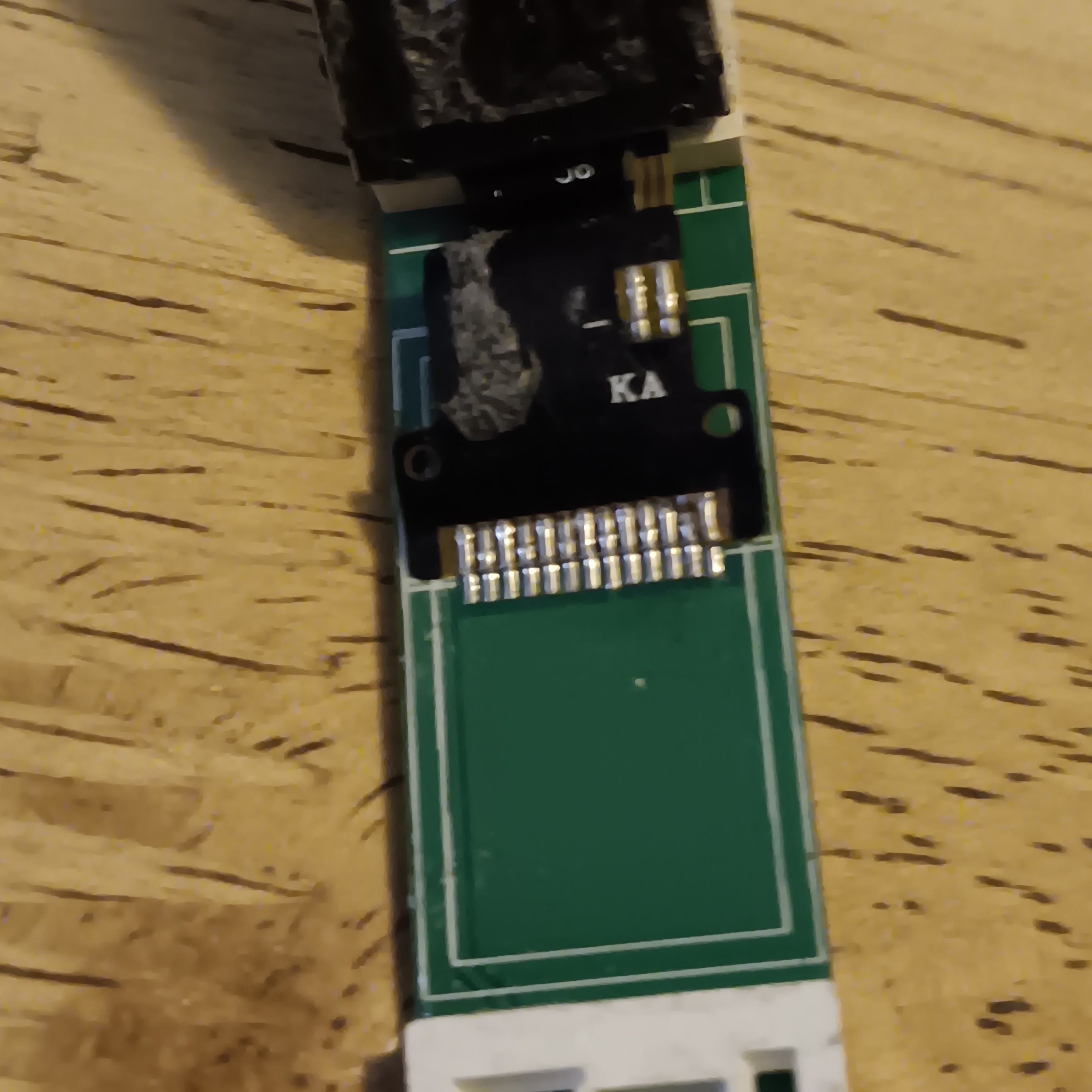
Next I continue to remove parts until I'm to the bare circuitry. Theres quite a few ics that I will look into further later, what looks like a microphone, some possible heating coils and a right angle connector to the screen.
I did get quite a bit of juice on my hands so I would advise using gloves when dissassembling these.
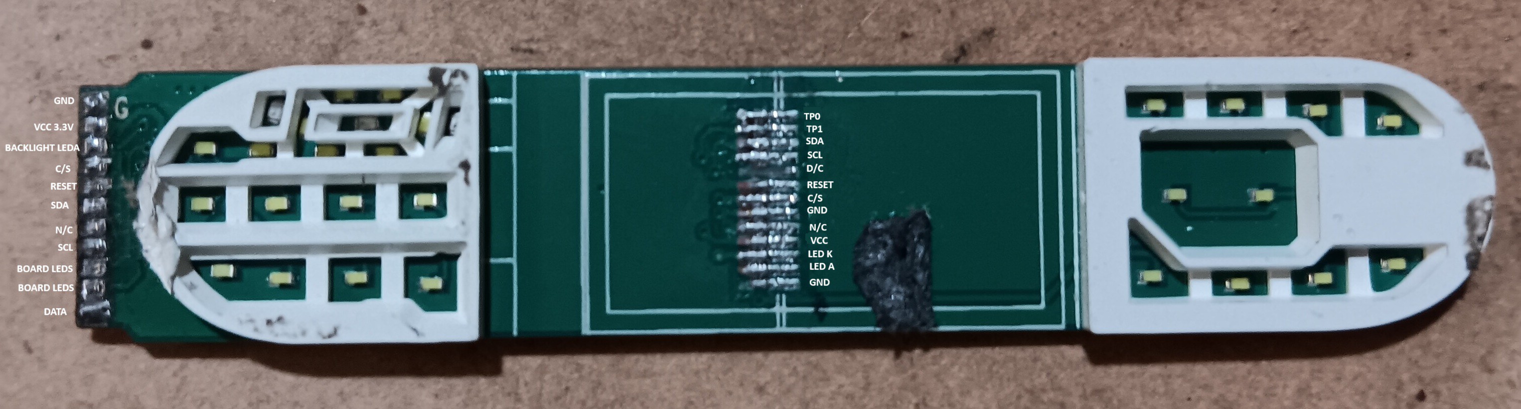
I have done quite a bit of work looking into the circuitry and display and I dont want to just know the innards, I would also like to be able to reuse the display as well. This is going to be a process so I will post more in the logs as time goes on.


 sapir
sapir
 Anders Nielsen
 daniel.bryand
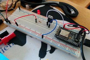
 WJCarpenter