STARTING
Since RF design can be tricky, I began by building some small RF test circuits (filters, microstrips, amplifiers, etc.) to make sure reality matches theory.
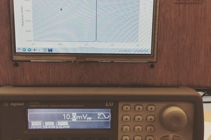
I etch the PCBs myself using 1.6 mm FR4 as the substrate, with a full ground plane on the bottom layer. For simulation I use QucsStudio, and I have access to a small but decent 4GHz VNA and a test receiver.
THE PROJECT
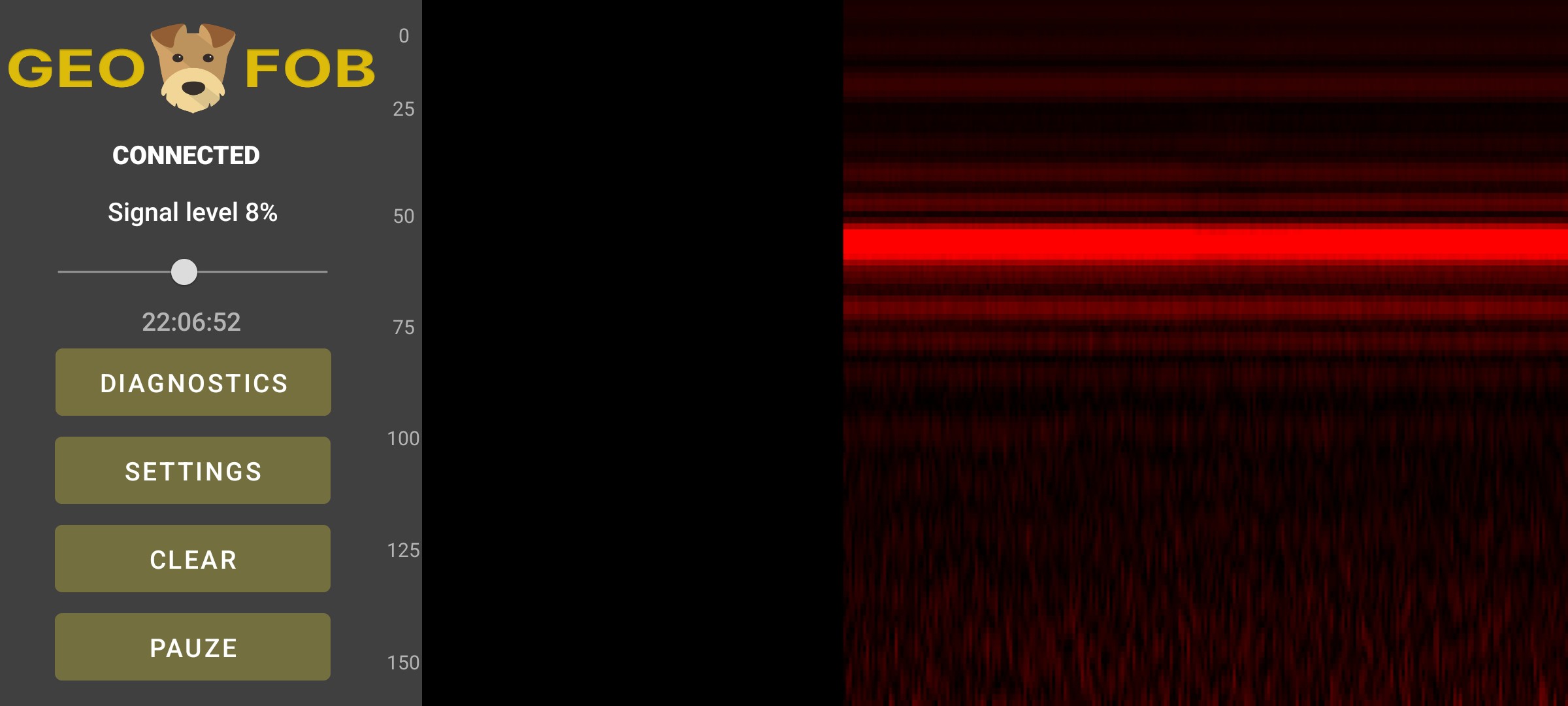
Over the past year, I built something that “works,” but not quite good enough. It gives repeatable results when used on soil, but when I dig, there’s nothing there. However, when I place the device on the concrete floor of the first story of my house, it clearly detects people in the room below.
So I think it’s time to step back and get some advice.
WHAT COULD BE WRONG?
The issue could be in several areas:
-
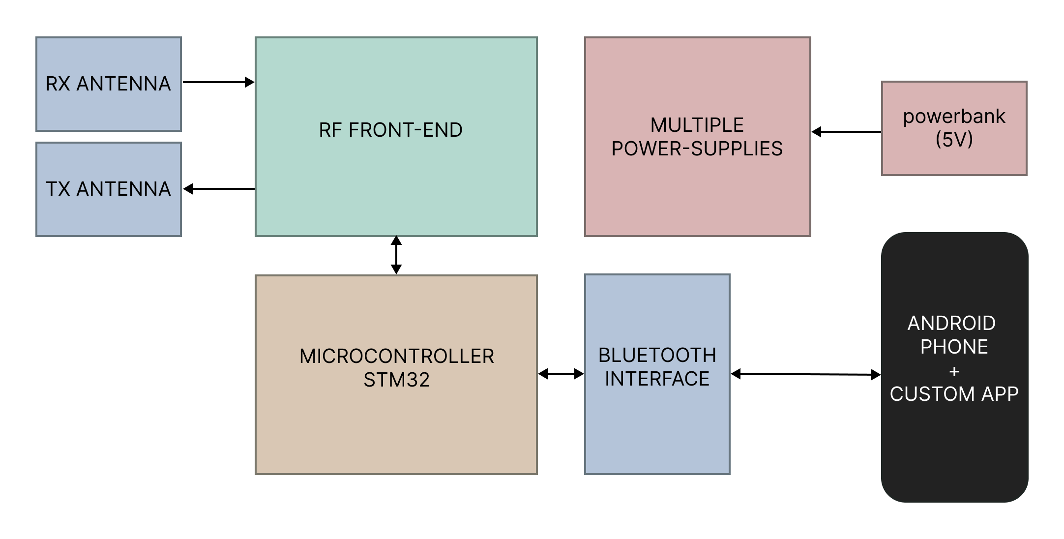
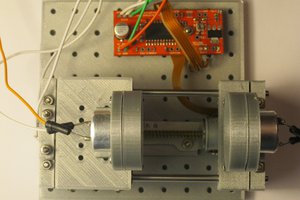
The RF front end
-
The antennas (reflections, isolation, ground effects, or distance from the ground—too close or too far)
-
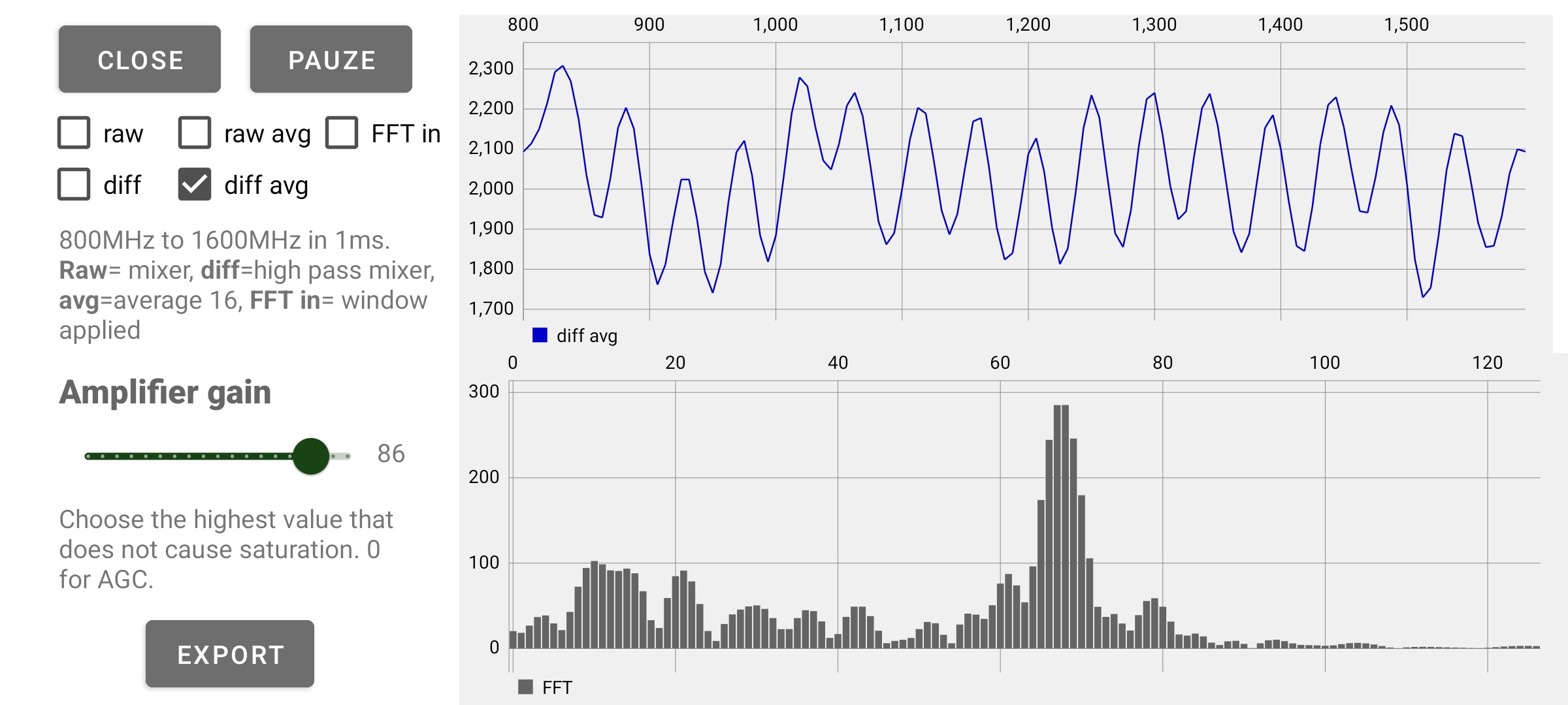
The operating frequency (I chose 800-1600MHz to keep the device portable and because of the AD8347’s minimum frequency, but it is probably too high)
-
The data analysis stage
APPROACH TO IMPROVE / LEARN
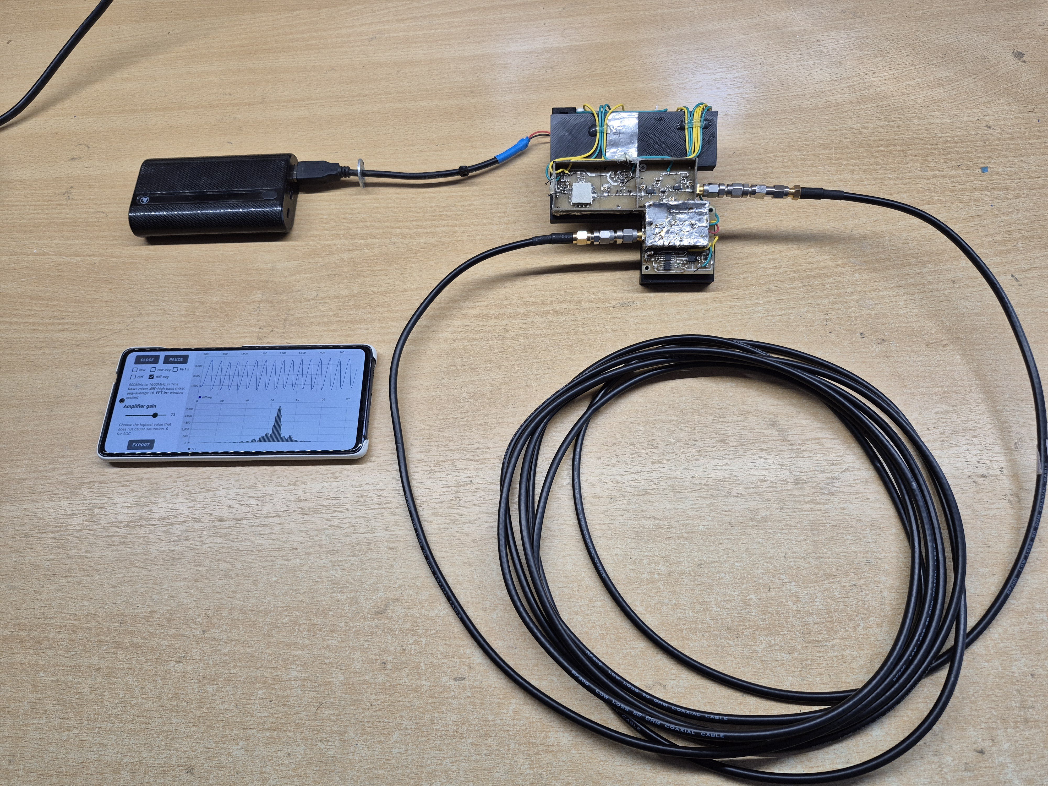
My first step is to confirm whether the electronics work as expected. I plan to replace the antennas with a coax cable and attenuators, then share the schematics along with measurement results to get feedback. From there, I’ll decide on the next steps.


 Dan Kisling
 Jovan
Jovan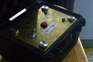
 Andrew Ferguson