 Stephan Walter
The oscillator output idles near the upper supply rail and produces low-going pulses.
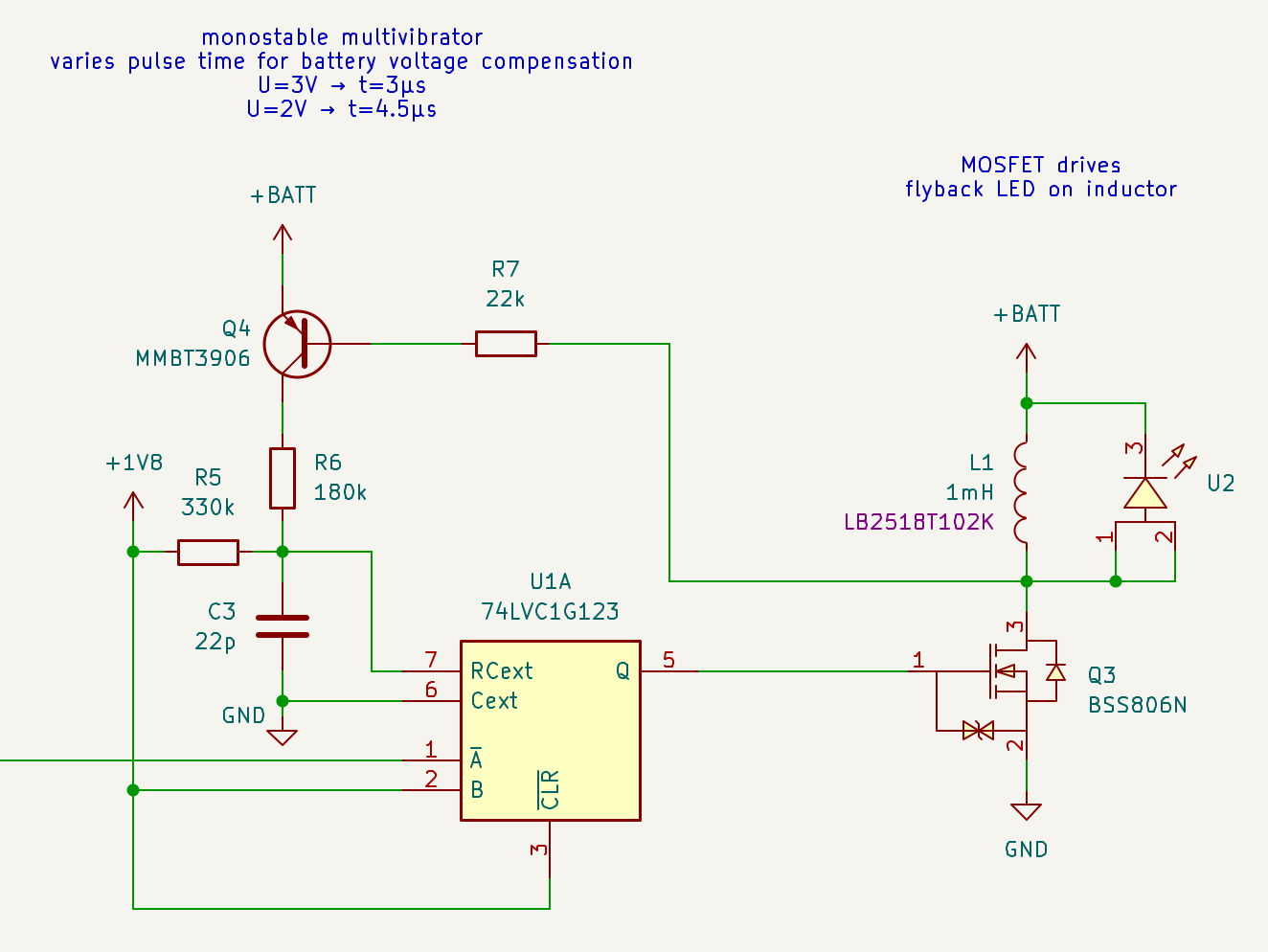
The pulse duration can be influenced somewhat by the choice of passives, but such fiddling also influences the oscillation frequency. It's best to separate the oscillation and pulse generation.
As in the previous work by others, the 74LVC1G123 by TI or Nexperia is chosen here. The Nexperia datasheet includes a logic diagram.
Another possibility to explore would be using two NAND gates - 74AUP2G00 should be suitable but I haven't looked into power consumption.
The pulse length is calculated from the desired LED current and the inductance value:
I'm sticking to the same values as Christoph: L=1mH, IRMS=5mA, Ipeak=9mA → ∆t=3µs.
A low capacitance value for Cext (C3) reduces the amount of charge that gets "thrown away" for each pulse. As expected, there is a resistor R5 through which the capacitor is charged to Vcc.
As the battery voltage drops, the pulse duration needs to be increased to maintain the same LED current. This is achieved using Q4 and R6. During the pulse, the PNP transistor switches the resistor to charge the capacitor quicker to the higher battery voltage. (A p-channel MOSFET might work as well, but the 3906 is already used for the oscillator).
R6 has to be switched to avoid continuous current flow in the idle state, via R5 and through the body diodes of the 123's MOSFETs at the RCext pin.
Discussions
Become a Hackaday.io Member
Create an account to leave a comment. Already have an account? Log In.