 Hulk
HulkThe ESP32-C3 Based Parking Assistant is an advanced parking sensor system that utilizes the ESP32-C3 super-mini micro-controller to provide accurate distance measurements and parking assistance. This is the third iteration of my previously released parking assistant videos. This parking assistant system uses ultrasonic sensors to help drivers park their vehicles accurately by providing visual and audible feedback about distance to the obstacles.
Components Required

- [Buy Now] For this project I am using an ESP32-C3 Super Mini single core microcontroller which has a small formfactor and also includes Wi-Fi and Bluetooth (Arduino Uno or similar microcontroller).
- [Buy Now] A HC-SR04 Ultrasonic Sensors (3-4 units)
- [Buy Now] A 24 LED NeoPixel Ring
- [Buy Now] A TM1637 7-Segment display
- [Buy Now] A Buzzer
- [Buy Now] A 100 ohm Resistor
- [Buy Now] A mini AC-DC 5V Adapter
- And mounting hardware printed using a 3D printer
Circuit Diagram

The wiring setup is pretty straightforward:
- Connect the microcontroller's Pin 4 to the buzzer
- Connect Pin 3 to the NeoPixel ring
- Wire Pin 2 to the Trig pin and Pin 1 to the Echo pin of the ultrasonic sensor
- Connect Pin 8 to CLK and Pin 9 to DIO of the TM1637 7-segment display
- Finally, connect all the positive (+) terminals to the power rail and all negative (-) terminals to ground
Breadboard Testing

Board and Library
-------------------
For the project to function, we first need to install the "ESP32-C3" board from the board manager. Additionally, we need to install the "TM1637Display.h" and "Adafruit_NeoPixel.h" libraries via the library manager.
I began by testing each component individually with the ESP32-C3 board to verify their functionality. Once all modules were confirmed to be working, I connected all of them to the ESP32 board and uploaded the program to orchestrate their combined operation. All source codes for this project are available on my GitHub repository.
We'll begin the "Parking Assistant" code by importing all the required libraries. Then, in the variable declaration section, we will define all pin numbers and the initial sensor values, making them globally accessible.
In the setup() section, the code first establishes a Wi-Fi connection to my Raspberry Pi-based home server. This feature is optional and can be disabled simply by removing or commenting out the relevant code section.
Following the network initialization, all pin modes (INPUT/OUTPUT) are defined, and the necessary hardware modules are initialized.
The loop() section operates continuously, performing two primary tasks:
It reads the distance from the ultrasonic sensor and outputs the value to the 7-segment display.
It also controls the NeoPixel LED color and number based on the measured distance, providing a visual indication of the approaching vehicle.
The system detects when the vehicle is stationary by monitoring for a stable distance reading. Once parked, the NeoPixels enter a "rainbow" animation mode before both the 7-segment display and NeoPixels power down.
The Board

This is the 2D and 3D representation of my board. Initially, I designed it with just the circular PCB, but in the final iteration, I incorporated an additional PCB dedicated to the ultrasonic sensor.
If you'd like to get started with PCB design, I have a step-by-step guide in "Tutorial No. 45: Transformers PCB BADGE", the link is in the description below.
Soldering

Lets starts by soldering the resistance to the board. Then lets solder the ESP32-C3 microcontroller to the board. Since I care a lot about my ICs and micro-controllers, I never solder them directly to the board. In case of an ICs, I always try to use IC bases or if a base is not available I use female pin-headers. (This avoids direct soldering and allows for easy replacement). Then, let solder the buzzer followed by the AC-DC 5V Adapter to the board. Once thats done let solder...
Read more »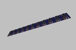
 FuzzyNoodle
 Arnov Sharma
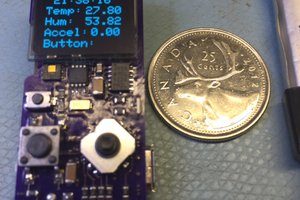
 0miker0