 fcipaq
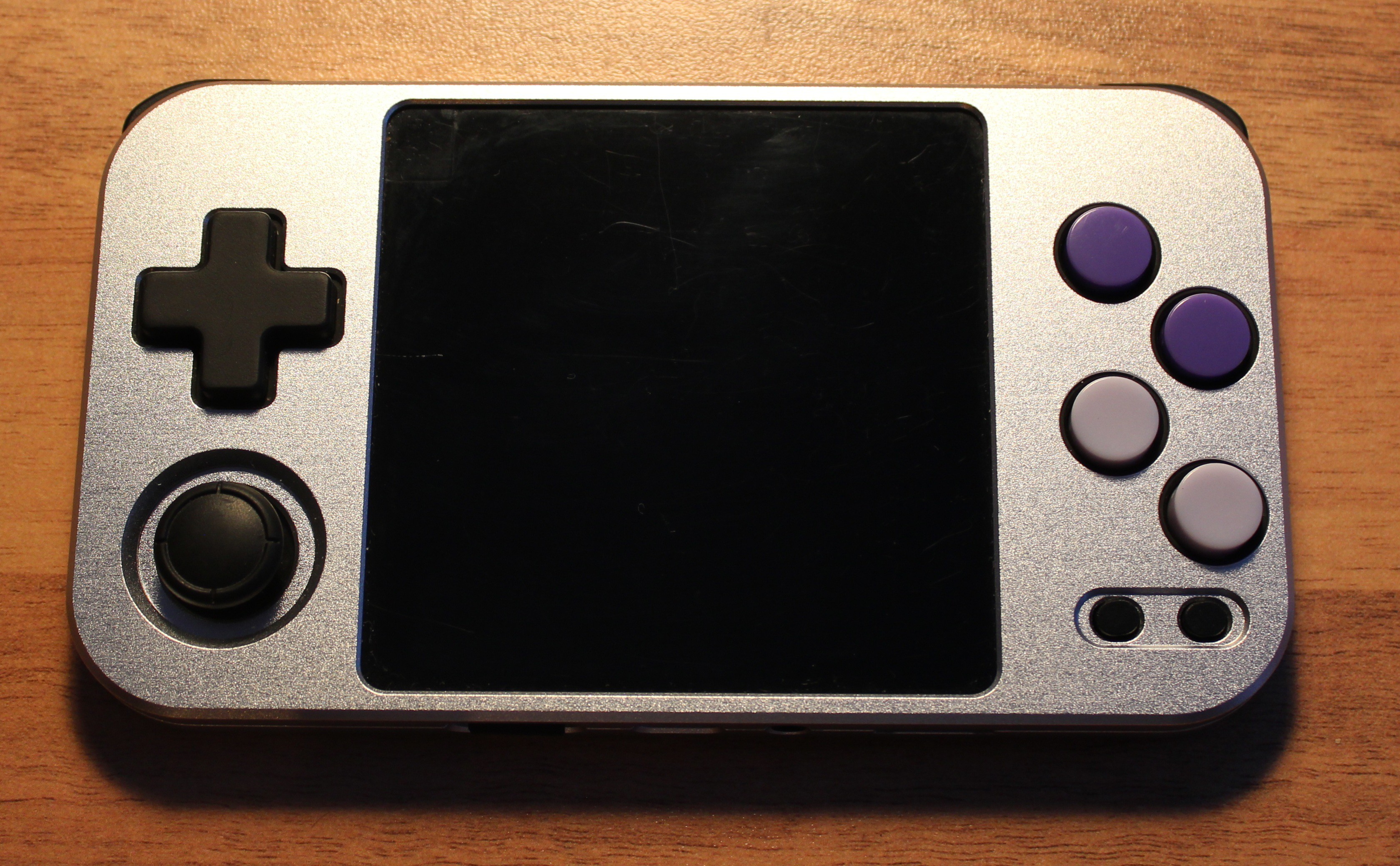
I wanted to create an open-source retro gaming handheld that doesn't suck and looks like a premium device, yet features all the customization possibilities one (I) could dream of.
I focused on a design that makes it easy for you to build your own. Thanks to Michele Santucci I think that we're getting really close to that goal now.
I really like the simplicity of an MCU gaming handheld, including the "instant on" feature.
A quick overview over the specs:
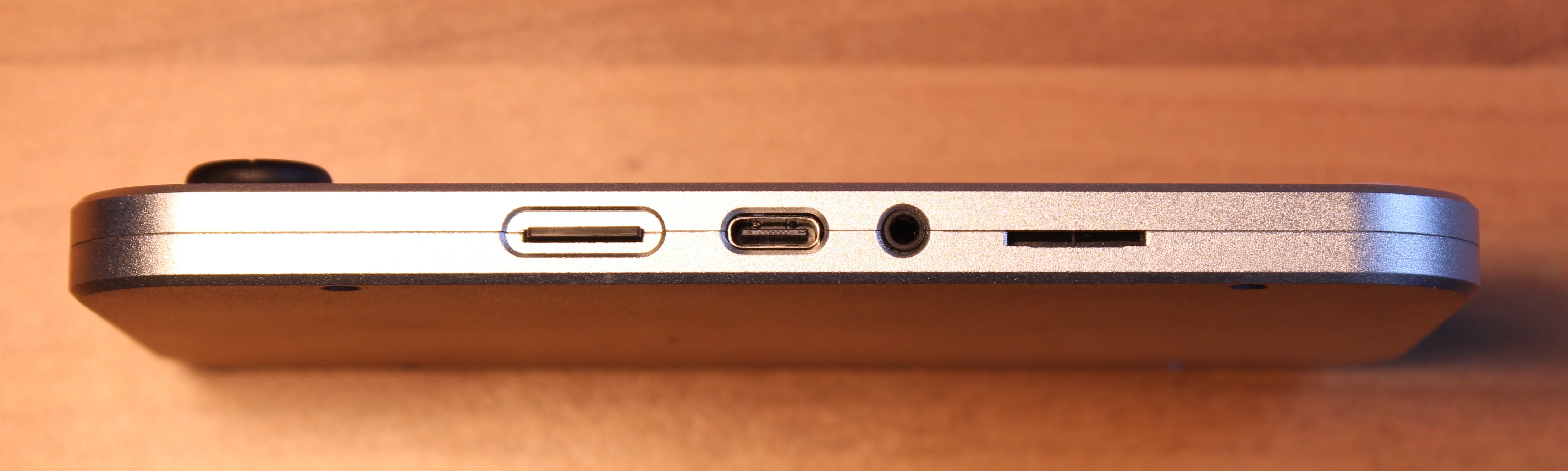
- aluminum shell (*swish*), dimensions: 148 mm x 78 mm x 10 mm
- 4 inch 720x720 display with RGB interface (that's 254 ppi !)
- I2S mono audio amp and 2.5mm headphone jack
- PSRAM support (I'm using 8 MB in the prototype)
- SD card slot (double functions as SWD debug interface)
- DPAD and analog stick, ABXY, start, select and shoulder buttons, reset button
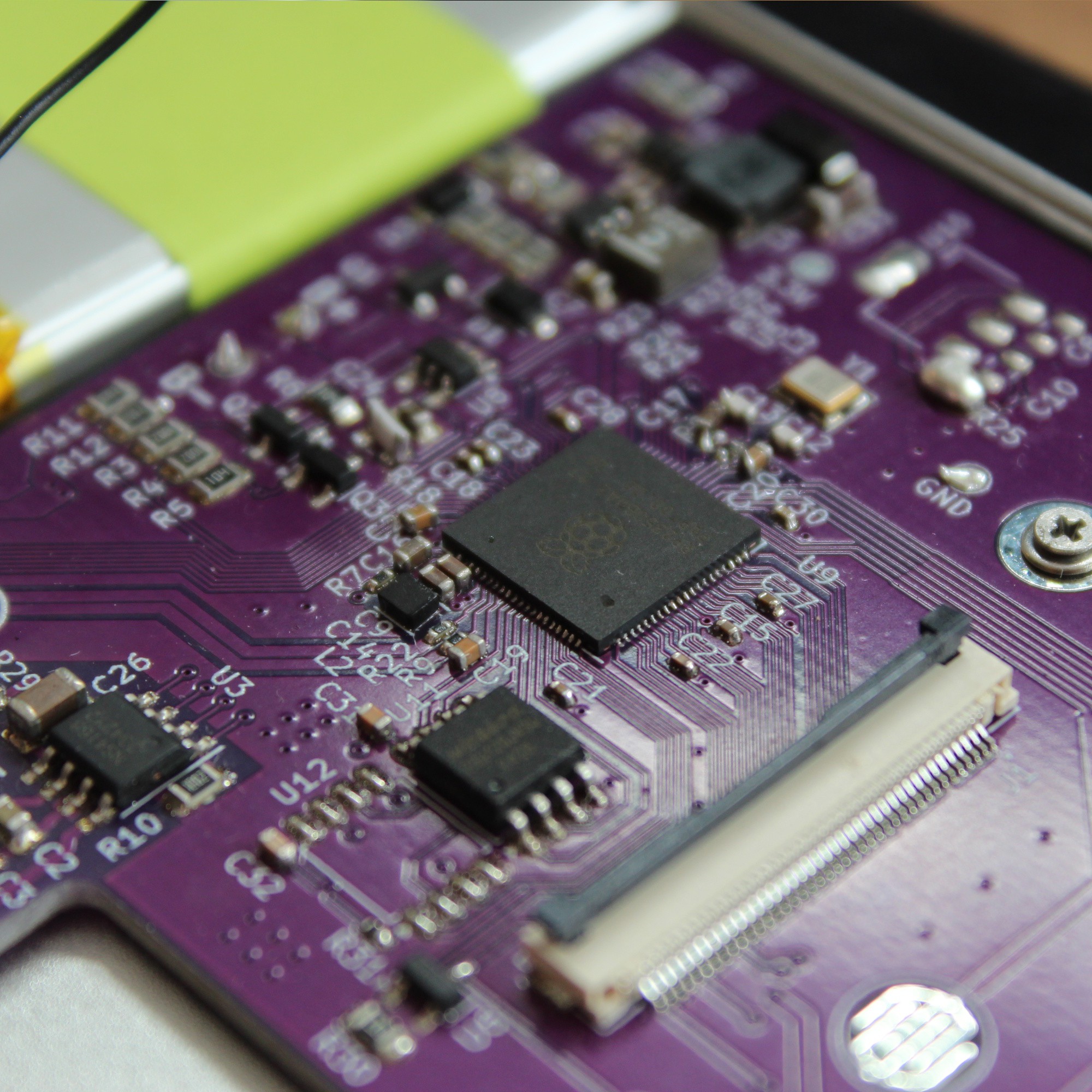
- RP2350B CPU
- 900 mAh LiPo battery for up to 4.5 hours of retro gaming
The RP2350 is truly impressive. Despite having a relatively small number of peripherals compared to the ESP32-P4, the careful choice and versatility of its peripherals make the chip a formidable engine for retro gaming.
PCB
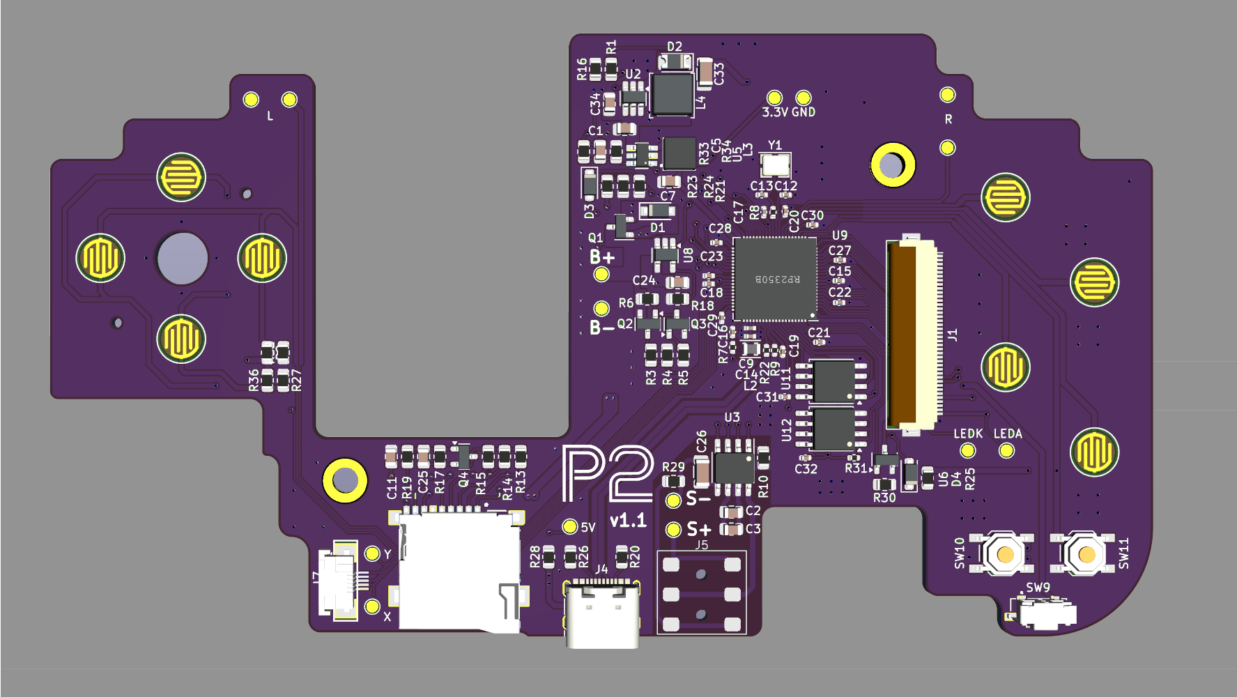
The PCB is a 1.6 mm, double-sided board based on a reference design for the RP2350. Careful routing allowed me to keep it as a two-layer board, which reduces production costs in case you want to build one of your own. It has a 3.3V buck converter for the main voltage supply, a boost converter for the onboard LCD, and a LiPo charger.
It's consuming about 200 mA when running (screen on and sound playing). And 50 uA when powered off (discharging the battery within two years).
Case
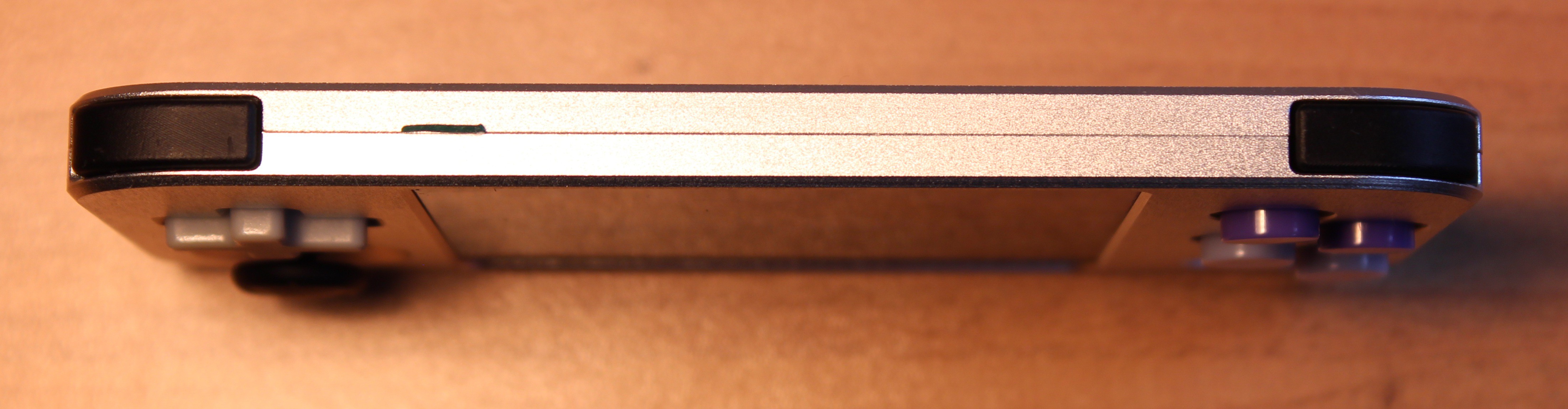
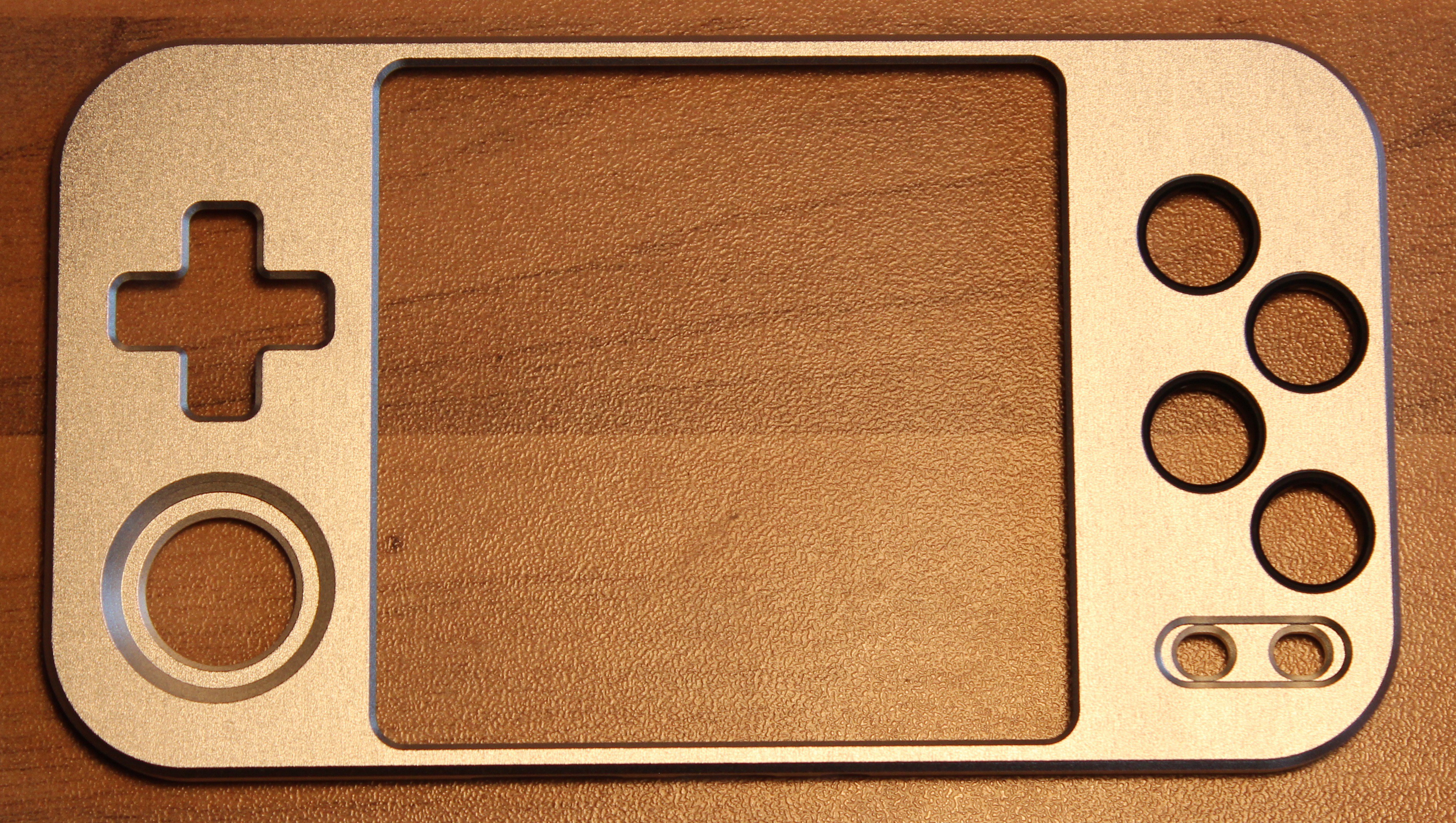
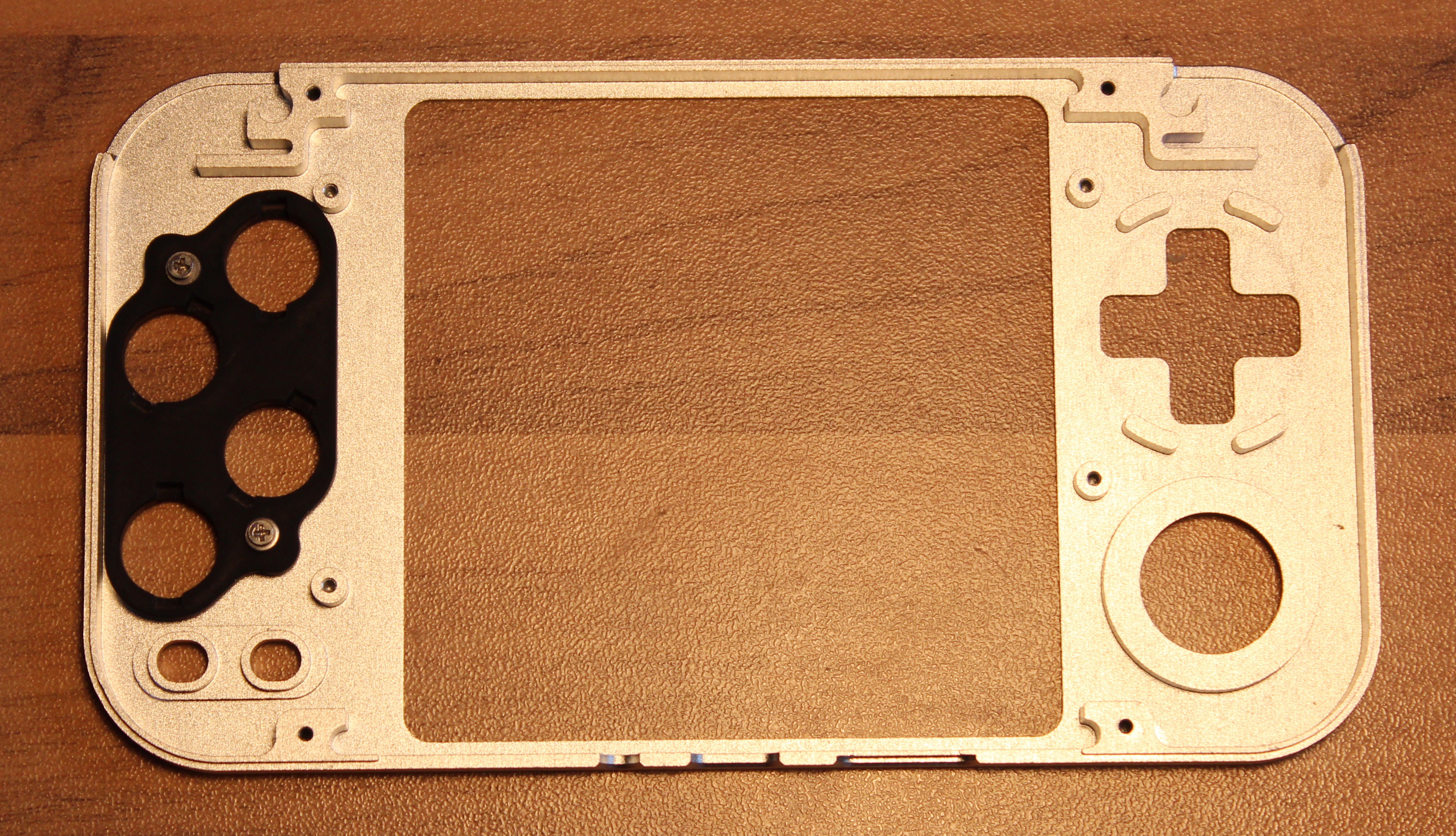
The case is CNC-machined from aluminum. It features a button bearing so that the buttons don't scratch against the metal case (scratches like we have seen on some commercially available handhelds impeding smooth movements of the buttons). You can have it machined in different colors just to your liking. It feels very sturdy and premium and I'm confident it's built to last.
DPAD
The DPAD was pretty hard to get right and I had troubles with false diagonals. There were like eight iterations or so (see the video about the ESP32-P4 version if you're interested in that).
PSRAM
I was able to get around 90-100 MHz out of the PSRAM chip though it's specified to run at 104 MHz. Not sure if that's my design, it's definitely not a superb hi-speed PCB design but then again, the PSRAM runs at roughly 100 MHz (the reference design placed the PSRAM right beneath the flash chip but that would have required the board to be assembled from both sides, raising the costs).
SD card
The SD card is tied to the chip via SPI. I had no issues running the SD card at 25 MHz, which gave me read/write speeds of 2.5 MB/s with my Sandisk card.
Debug interface (SWD)
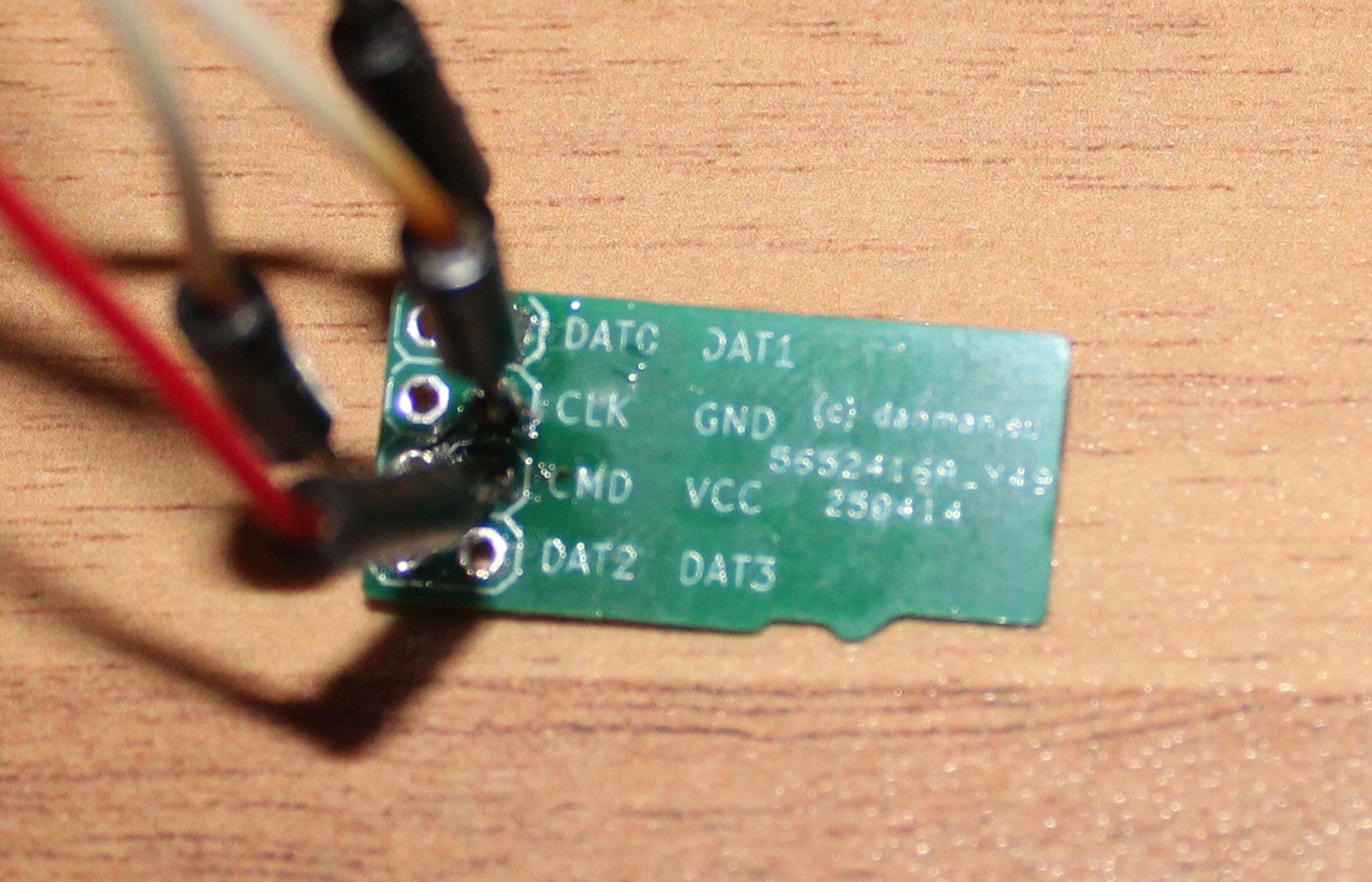
For easy development, the SD card slot doubles as the SWD debug interface. The SWD and SWCLK lines are routed to the unused SD card pins in SPI mode. Also, UART output can be forwarded to the SD card slot. You can for example use a Picoprobe. Simply plug an adapter into the SD card slot and you're ready to start the bug hunt. However, it goes without saying that you cannot use SWD and and the SD card simultaneously.
Display
The first question that might come to mind is: Why would anyone build a 720x720 pixel display into a device powered by a microcontroller with no more than half a meg of RAM? Great question! I designed the device with the idea that it would be a retro gaming console. One of the major aesthetics of modern pixel art is blocky visuals, in contrast to the more flyscreen-like optics of the past. Driving the display at 3x integer scaling gives you phenomenal visuals, and the super-high pixel density leaves no chance for eye strain.
In order to achieve thin bezels above and below the screen, the display must be mounted at a 90° rotation. Therefore, a driver is needed that can scale and rotate the screen....