 With Z80 CP/M or FUZIX
The RP2350A A4 stepping includes fixes for the E9 errata as an improvement over previous versions. While the Raspberry Pi Pico 2 incorporates this chip, experimental information remains scarce. After sharing progress on X.com, I decided to leverage @74th's excellent open-source board design to document the detailed process.
Materials:
- RP2350A A4 stepping Chip:
- Board and Component Set: Used the open-source “rp2350a-full” board and corresponding component set provided by 74th (@74th). https://74th.booth.pm/items/6483839 , Gerber data is available at https://github.com/74th/rp2040-dev-board/tree/main/rp2350a-full
- Soldering Tools: Fine-tip soldering iron, flux.
- Test Environment: Oscilloscope, multimeter, host PC with Raspberry Pi Pico SDK installed.
Hand Soldering:
The QFN-60 package has a narrow pin pitch and thermal pads, making hand soldering difficult. Please refer to this link: https://74th.hateblo.jp/entry/2025/01/12/222618
Initial Startup:
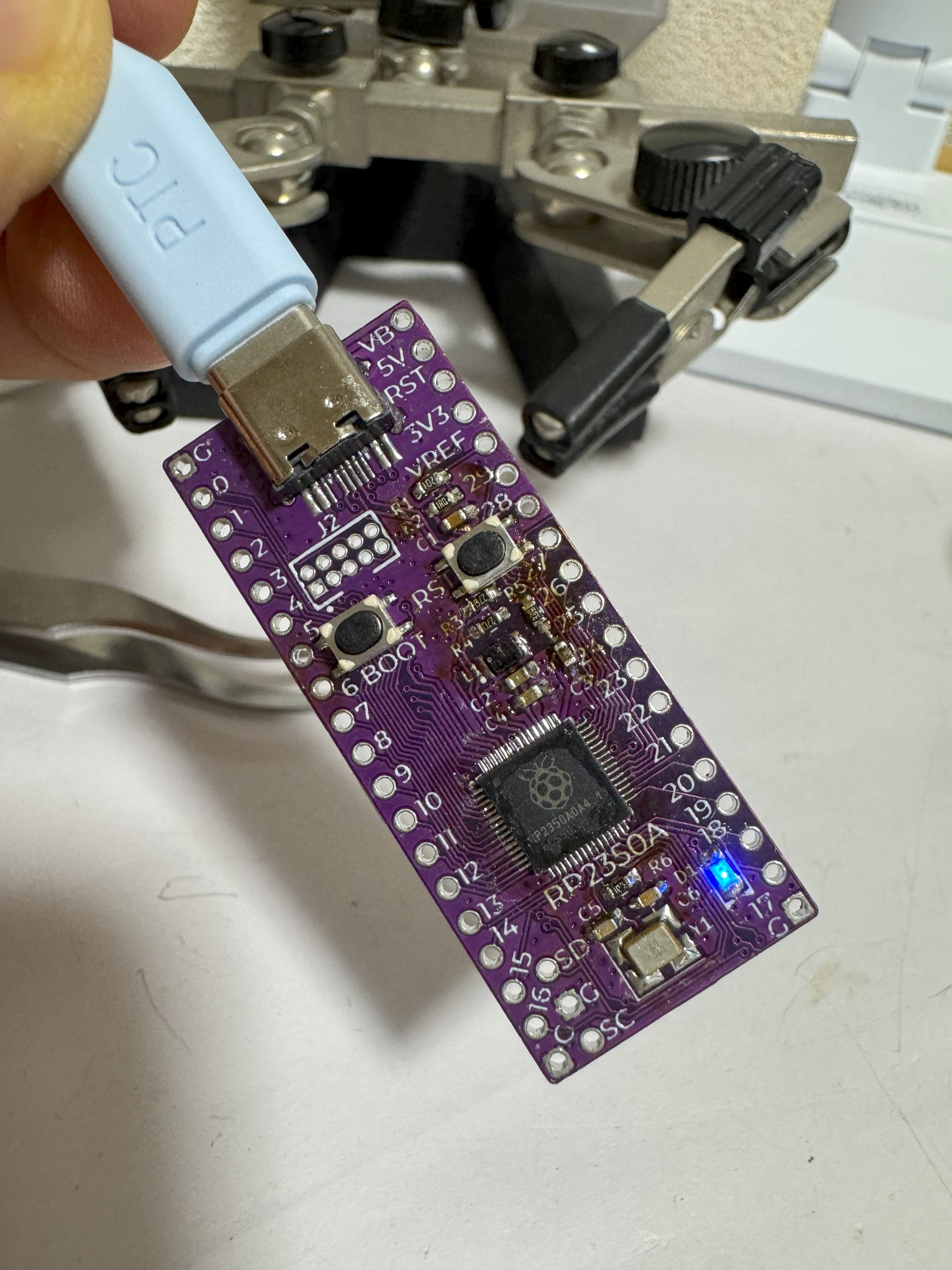
- Connect the board to the host PC via USB.
- Use the Pico SDK to upload the basic “Blink” firmware and verify the chip's operation. https://pbs.twimg.com/amplify_video_thumb/1961882663780052992/img/ZRLO8U-SAQSLA2bB?format=jpg&name=large
- GPIO check using mcu-pin-check-firmware/rp2350. https://github.com/74th/mcu-pin-check-firmware/tree/main/rp2350
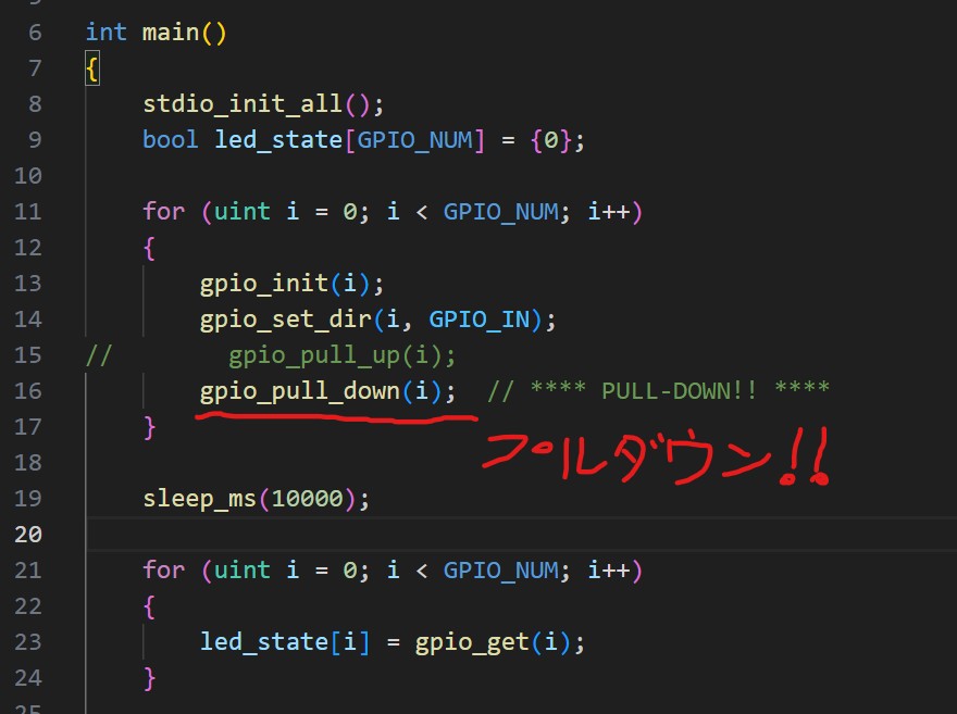
E9 Errata (Pull-Down) Verification:
The E9 errata in the conventional RP2350 A2 stepping caused issues with pull-down settings. To verify the fix, we modified the mcu-pin-check-firmware and confirmed the correction.
Conclusion:
Using the open-source “rp2350a-full” board and component set by 74th, we successfully obtained the RP2350A A4 stepping chip, hand-soldered it, and tested it. The E9 errata (pull-down) fix has also been verified, and the chip operated stably. Thank you to 74th (@74th) for this outstanding open-source contribution! I hope this project serves as a useful reference for RP2350A A4 experiments.