 Michael Morton

Building an entire CPU from scratch has been the "Holy Grail" of my electronics hobby for at least the last ten years or so. Now, after a lot of time, research, and effort, I have finally succeeded!
This project showcases a simple 8-bit one-instruction CPU that I built over the course of about 4 months in the summer of 2025. The CPU runs the subleq instruction set, which, surprisingly enough, achieves Turing-completeness with just one instruction. Some goals for this project were:
- Build as much of the CPU out of discrete components as feasible (minimize the use of integrated circuits)
- Make getting output from the CPU as painless as possible
- Get a "Hello world" program running
I think I did a decent job accomplishing these goals. For those of you who don't want to read through all the details of this project, I do have a video up on my YouTube channel that explains how I made this processor.
For those who wish to continue reading, a detailed overview can be found below.
The subleq instruction takes three arguments, A B and C, each representing a location in memory. The subleq instruction first subtracts the value at address A from the value at address B, then stores the result back at address B. Then, if the result of the subtraction was less than or equal to zero, then the program jumps to address C. With some clever permutations of this one instruction, it is possible to simulate any CPU operation we want.
Because the CPU uses such a simple instruction set, it was able to be implemented with very simple hardware. The machine only has 4 8-bit registers, three of which are asynchronous and hence much simpler to build than would ordinarily be required. The only synchronous register is the program counter. A list of all of the components of the CPU is outlined below:
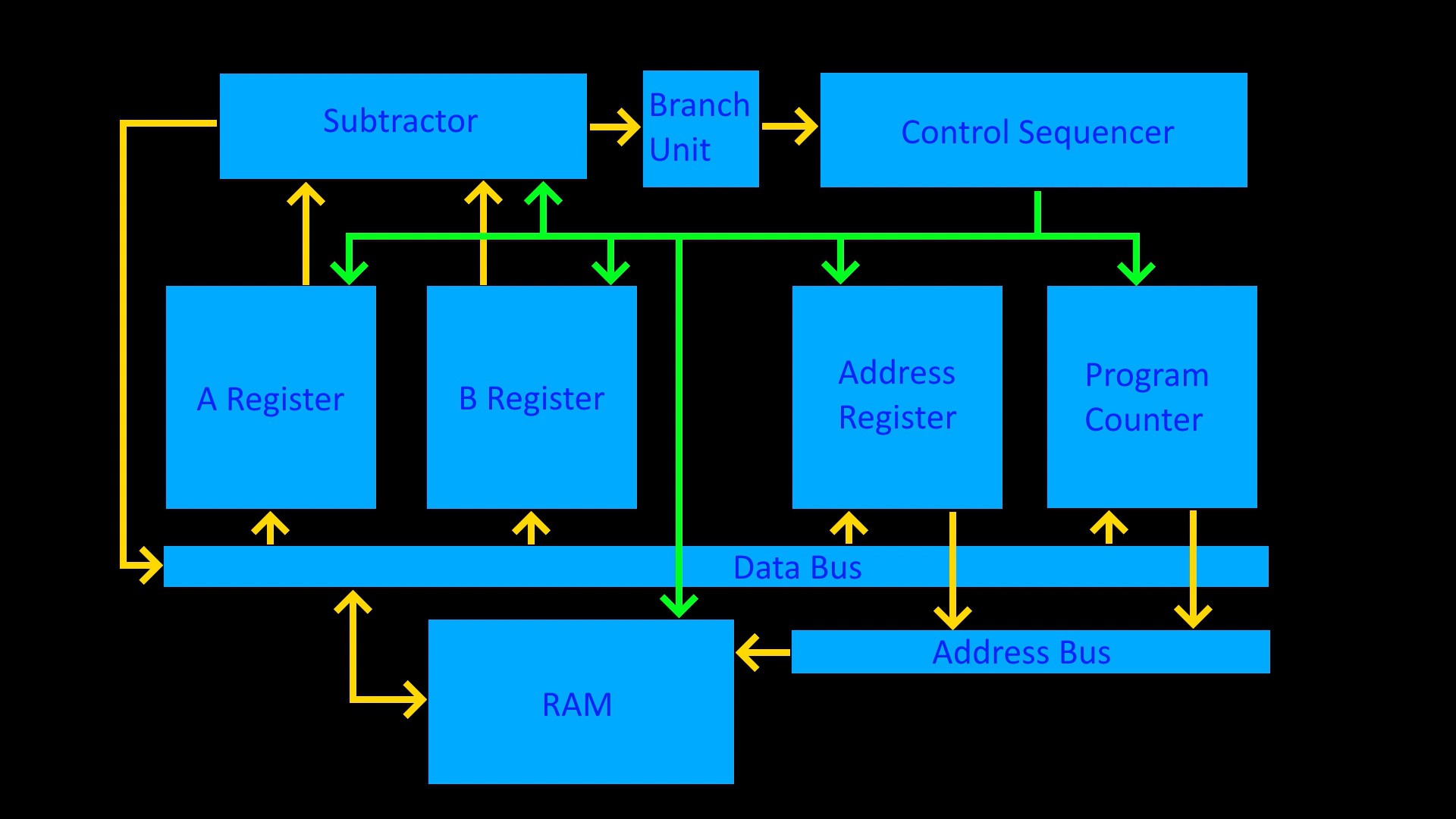
- The A and B Registers: two asynchronous registers that store operands for the subtractor from the data bus
- The Subtractor: subtracts the value of the A register from the B register, and optionally outputs the result to the data bus
- The Branch Unit: decides if the program should branch based on the output of the subtractor
- The Address Register: an asynchronous register that acts as a pointer for fetching A and B operands for the subtractor
- The Program Counter: a synchronous counting register that is used to fetch instruction operands during execution
- The Control Sequencer: contains a 6-stage ring-counter and an instruction decoder to activate control lines in the correct sequence to execute the subleq instruction
- RAM: the only Integrated Circuit on the machine (not counting the LCD display)
- Data bus and Address bus: two 8-bit busses, one for data and one for memory addresses; the machine can therefore access 256 bytes of memory
A block diagram of the CPU's architecture can be found below:
On this architecture, it is possible to execute the subleq instruction in six steps:
1) Using the program counter, load A into the address register, and increment the program counter
2) Using the address register, load the value stored at address A into the A register
3) Using the program counter, load B into the address register, and increment the program counter
4) Using the address register, load the value stored at address B into the B register
5) Using the address register, store the output of the subtractor at address B
6) If the program needs to branch, then use the program counter to load C into the program counter. Otherwise, increment the program counter to move to the next instruction.
Once the CPU architecture and instruction sequence had been designed, I decided to simulate the CPU at the logic gate level in Logisim before beginning the physical build. A screenshot of the Logisim circuit can be found below, and the full .circ file for the Logisim circuit can be found on my GitHub if you want to tinker around with it. ...
Read more »


 ammarbhayat28
 Tim Ryan
 Mitsuru Yamada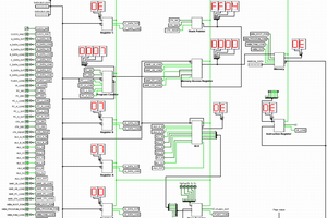
 Ruud van Falier
Good Work Michael - I am porting your Logisim design to H. Neemann's "Digital" simulator - so I can play around with it. Unfortunately I don't know Logisim enough to work with it..
Could you post the subleq source code for the fibonacci program please. I just need a small test routine to check my simulation.