 Abraham Jones
1. Designing the Hardware:
The first step in designing the hardware was for me to research components and select the ones that I thought would be sufficient. I wanted this project to run on 3.3V and draw as little current as possible, so I selected components that could meet these requirements.
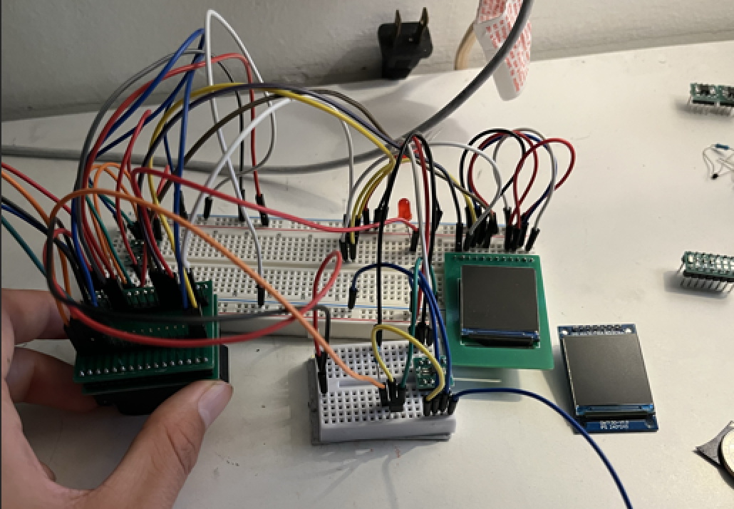
Next, I began testing the schematic. I wanted to use a breadboard so that I could easily connect and disconnect pins as I encountered errors. However, all of the components I was using were SMD, so connecting them to a breadboard would only be possible with a breakout board for each IC. So, I designed a PCB for each SMD device using JLCPCB. Below are the breakout boards for the ST7789 (display) and the DS1302ZM RTC (real-time clock).
2. Software:
https://github.com/MadCat67/Smart-Watch
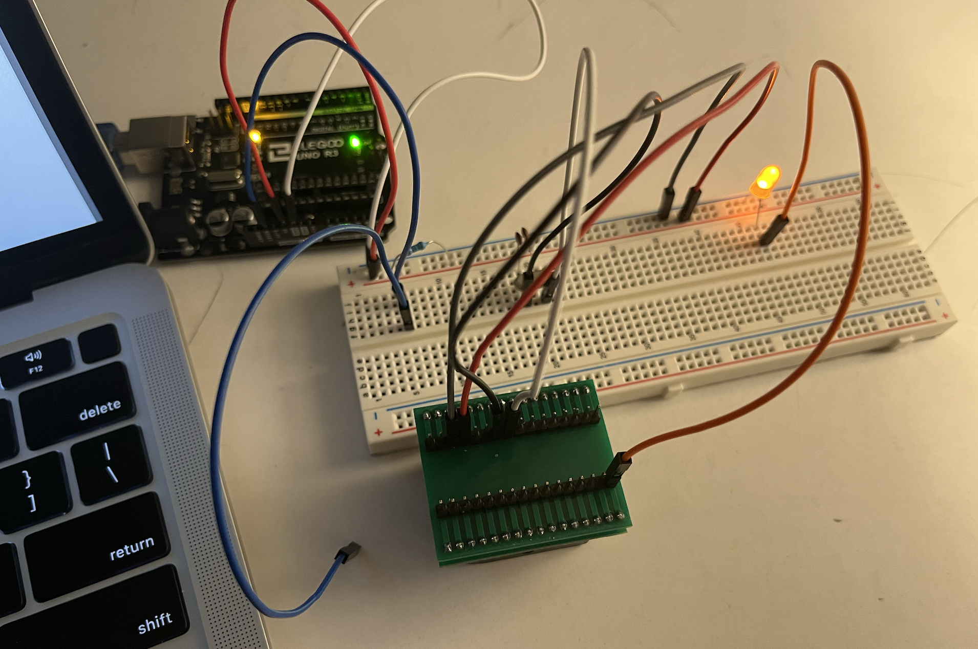
Once I had each component connected on the breadboard, I was able to begin programming the main microcontroller (ATmega328P-AU). To do this, I connected my laptop to an Arduino Uno to send binary code to the ATmega328P.
Programming the microcontroller was one of the most difficult parts of this project. Interfacing with all of the other devices was confusing, and one slight mistake could cause numerous errors. The most difficult things that I had to program were:
- An interrupt to turn on the microcontroller when the user presses the on button. This was difficult because I had never done any programming at this low level. However, turning on the ATmega328P with a hardware button from an interrupt was necessary to avoid excessive power consumption while the device was not on.
- Keeping the RTC time accurate. If the watch ran out of battery, then the RTC would turn off and lose track of the time, causing it to be behind when the battery gets recharged again. To fix this, I had to program the ATmega328P to detect when the battery got low and go into a sleep state so that the RTC wouldn't fully turn off.
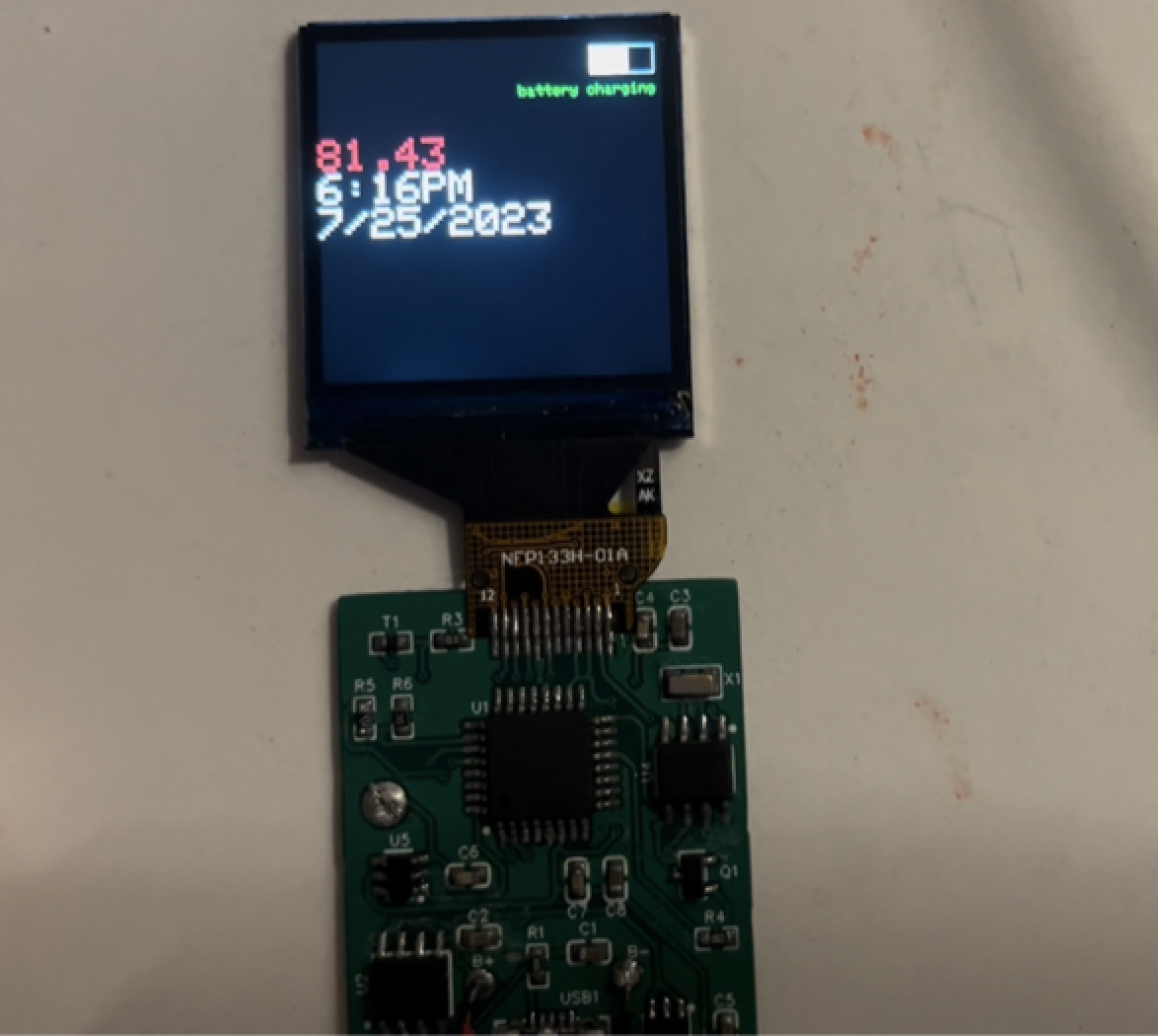
- Calculating temperature. The number printed in red on the watch's display is the room's current temperature. Calculating this required a precise reading from a voltage divider made with one resistor and one thermistor. The ATmega328P then had to calculate the temperature using some complex calculations.
- Calculating battery life. Similar to the temperature reading, the battery life was calculated by the ATmega328P using just a voltage reading, but this time from the battery. However, as the battery loses its charge, the output voltage drops in a nonlinear way. Additionally, some battery charge had to be reserved to prevent the RTC from shutting down and losing track of time. Therefore, calculating the battery charge was not easy and required careful calculations.
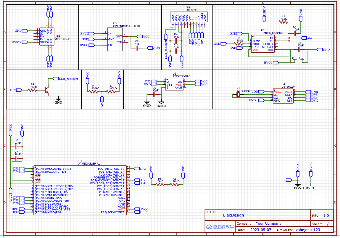
3. Final Schematic:
After I had verified that all of the software and hardware were working correctly, I could get started on making the PCB for the watch. To do this, I first had to make a schematic with EasyEDA. The schematic shows how everything is to be connected in the final version of the watch and serves as a guide for designing the PCB.
When designing the PCB, I had to ensure that each device would operate with minimal noise from the outside environment. This meant I had to carefully route signals apart from each other, as well as place decoupling capacitors between the VCC and GND pins of each device. Once this was complete, I was able to order the PCB and assemble the final version of the watch.
To solder everything to the PCB, I used a cheap soldering iron from Amazon, standard lead solder, and some liquid flux.
Smartwatch Schematic Summary
-
Main Controller
-
ATmega328P-AU (U1):
-
Acts as the central microcontroller.
-
Interfaces with peripherals (RTC, display, sensor, etc.).
-
Provides GPIO, I²C, SPI, ADC, and serial communication.
-
-
-
Power Supply & Battery Management
-
USB Input (USB1, Micro-USB): Used for charging and programming.
-
TP4056 (U2): Lithium battery charging IC, manages safe charging.
-
SPX3819M5-L-3.3 (U3): Low-dropout regulator, provides regulated 3.3V supply.
-
Battery (B+): Powers the system with backup from regulated 3.3V.
-
Decoupling capacitors (C1, C2, C5, etc.): Stabilize power supply.
-
-
Display
-
ST7789 (U6): TFT LCD display controller.
-
Connected via data/command lines from the ATmega.
-
LED_backlight circuit (R4, DP9): Provides display backlight control.
-
-
Real-Time Clock
-
DS1302ZM (U4): RTC module for timekeeping.
-
32.768 kHz crystal (X1): Provides clock reference for RTC.
-
-
Sensors
-
TTP223E (U5): Capacitive touch sensor IC for user input.
-
Supporting components (C6, resistors): Ensure stable sensor operation.
-
-
User Input & Interface
-
Touch input via capacitive sensor.
-
Display output via ST7789 TFT driver.
-
-
Supporting Components
-
Resistors (R1–R6): Used for pull-up, current limiting, and sensing.
-
Capacitors (C3–C8): Filtering, stabilization, and timing.
-
Test/programming headers (DP1–DP13): Expose MCU I/O pins for debugging.
-
-
Oscillators
-
Crystal oscillator (X1) for RTC.
-
ATmega328P internal/external clock sources used for system timing.
-