 Joseph Eoff
Here's the circuit again:
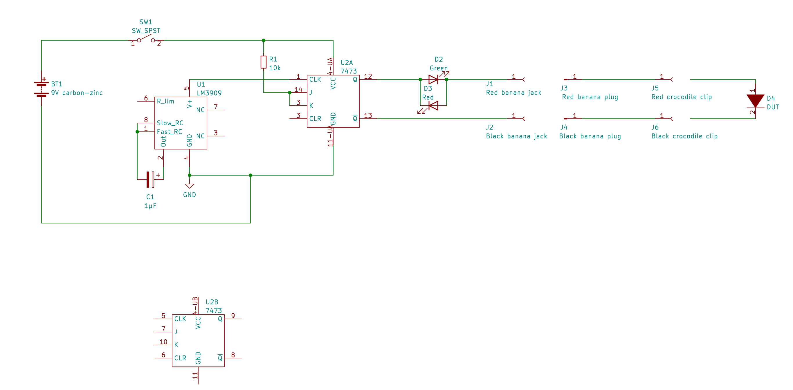
Let's count the abuses in the circuit.
Starting from the left:
- Powered by a 9V transistor radio battery with no regulator. The 7473 receives 9V from the battery (the absolute maximum for the 7473 is 5.5V)
- The LM3909 LED blinker IC has no LED to blink.
- The LM3909 is powered by the leakage current from the 7473 clock input. The datasheet says it needs a minimum of 1.15V to operate. It is operating here on something less than 1V.
- The clock signal to the 7473 is a 0.7V peak to peak signal. By the datasheet, a low is maximum 0.8V and a high is minimum 2V. Somehow, 0.7V is enough to trigger the clock.
- There's no decoupling capacitor for the 7473.
- The 7473 is driving the LEDs directly, with no current limiting resistor. This exceeds the output current limit for the 7473
- The LEDs are driven directly from the 7473 with no current limiting. This exceeds the LED current limits.
By all rights, the 7473 should just go "pop" and give up the ghost as soon as it is turned on. It doesn't.
The 7473 should burn out its outputs, driving current into a short circuit when the diode under test is bad. It doesn't.
The LEDs should go "pop" when the output is shorted. They don't. They blink happily.
The LM3909 shouldn't oscillate at all since it has no real power supply and what it does get is completely outside of the specifications. It runs.
The 7473 shouldn't react to the flaky clock signal from the LM3909. It does.
Some of that I can explain, some of it I can't.
The parts of it I do understand, I'll explain in a later post.
Discussions
Become a Hackaday.io Member
Create an account to leave a comment. Already have an account? Log In.