 Arnov Sharma


Unlike the full-fledged Raspberry Pi that comes with operating systems and multimedia support, the Pico is a microcontroller. That means no Linux, no built-in graphics stack, and no luxury of high-level emulation frameworks. Everything—from display handling to sound generation and ROM loading—had to be engineered from scratch. And that’s exactly what makes this build special. However, we are not really building the emulator from scratch; we are using an existing Pico GB project repository. All the circuitry has been built from scratch.
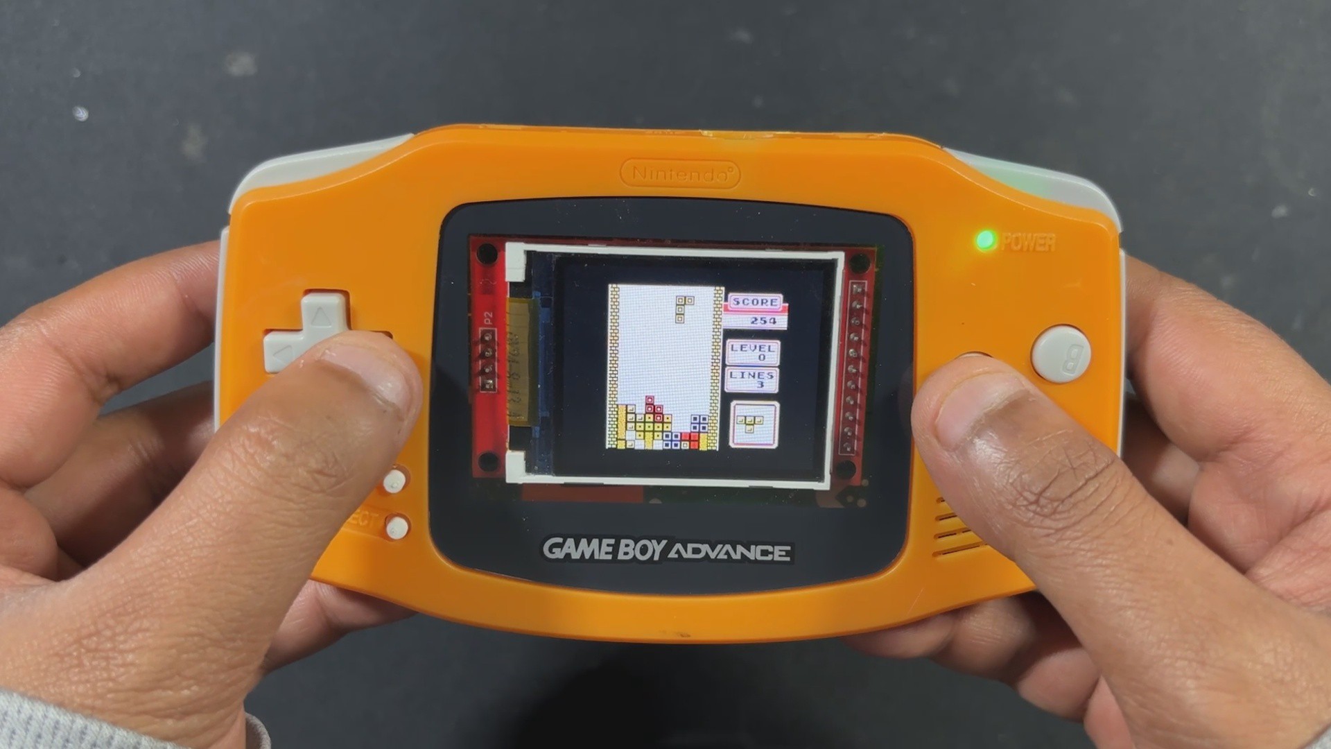
PiBoy Advance runs Game Boy ROMs directly from an SD card, displays them on an ILI9225 screen, and even outputs sound using a MAX98357 I2S Module.
The shell used in this project was arranged from a local marketplace in my city, which is the Lajpat Rai market. It's one of the biggest electronics marketplaces in India; it's in front of Red Fort, New Delhi, and here you can find a bunch of old retro games and related stuff. I even got an OLED PSP and PS2 from here, which I will be using in a future project.
By following the PICO GB pinout info found on their GitHub page, I was able to make a simple circuit that houses the PICO display and the sound module together along with buttons for controls.
Additionally, because we are making a handheld device, we had to provide a stable power source, so we added a power management circuit in our setup, which uses a LiPo cell to provide power to our PICO setup.
This article covers the complete build process of the PiBoy Advance project, so let's get started with the build.
Hardware


For our Game Boy Project, we're using the Pico-GB repository created by YouMakeTech; this version was a fork of the RP2040-GB Game Boy (DMG) emulator from deltabeard. Here the PICO serves as the brain of the project. I did try to use PICO 2 and even PICO W, but this only works with the PICO RP2040.
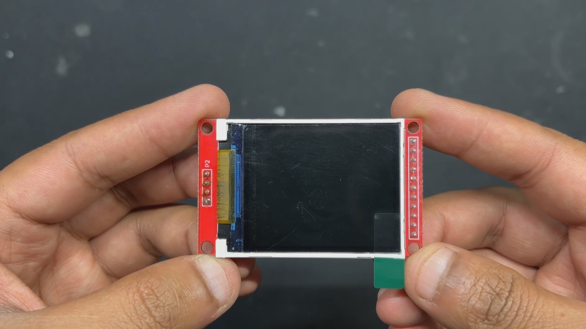
For the display, we have to use the ILI9225 display, which runs more than 70 fps, which is insane. The original DMG project didn't support audio out, so youMakeTech modified the original file and added a few key functions that include I2S sound, meaning we had to use an I2S amplifier module. For this, we chose the MAX98357 audio module that is connected to a small form factor 1W speaker, which will provide audio output for our device. a small fun fact, this small 1W Speaker is harvested from DF ROBOT'S unihiker k10 Dev board.
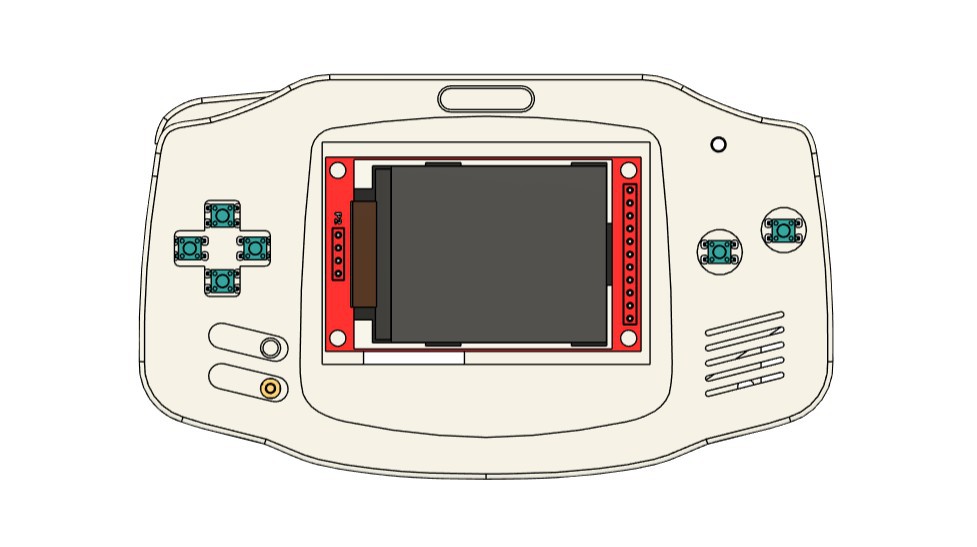
Game Boy Advance Shell

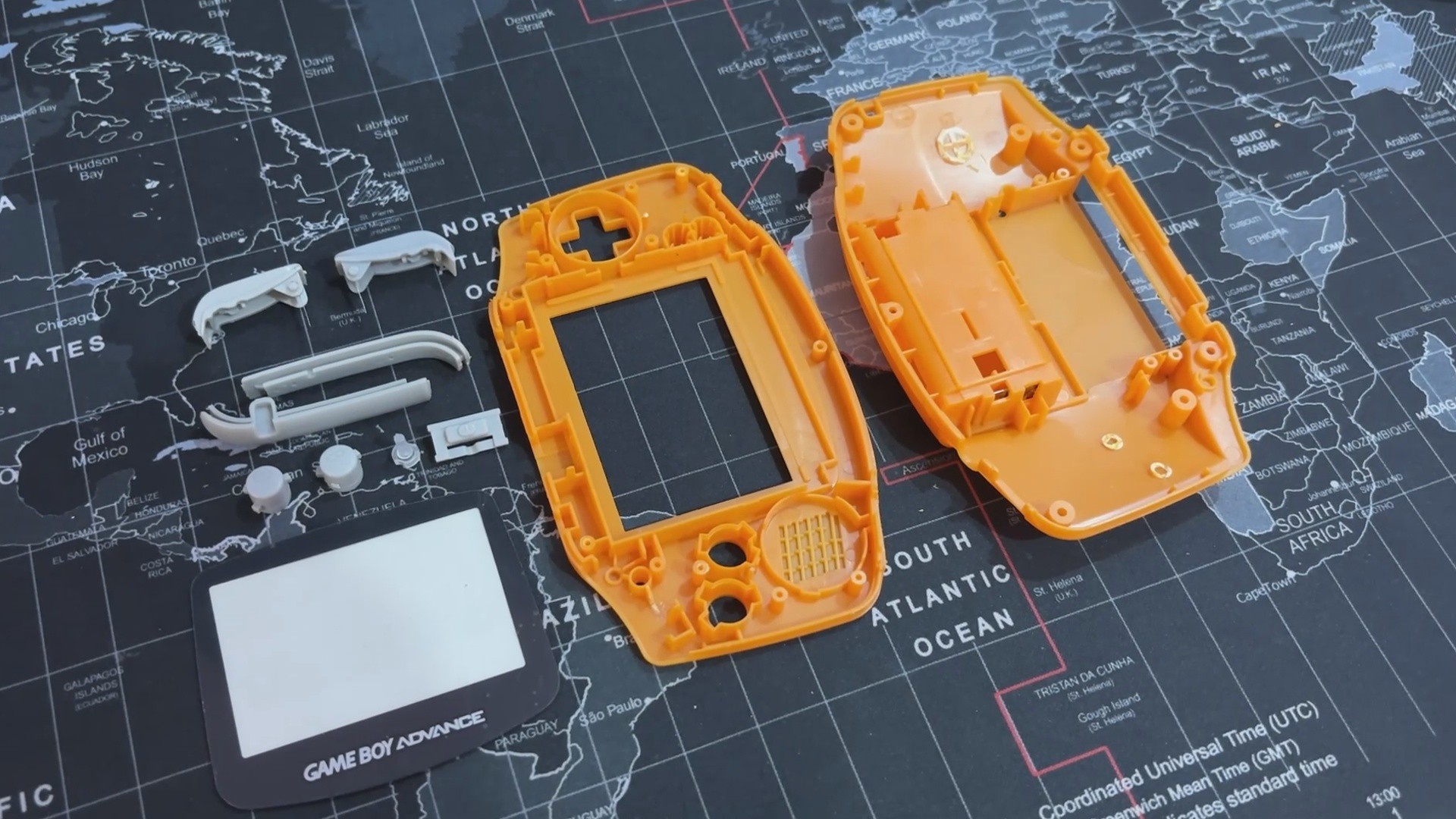
One of the most important parts of this project is the Original Nintendo Game Boy Advance replacement body kit, which I purchased from a retro game vendor that sells vintage consoles like the PS1, PS2, XBOX, and others at a local electronics market.
I saw this orange Game Boy advance shell while the seller was selling replacement body kits for handheld devices, and it made me think, "Why not build the entire Game Boy from scratch?" Since the body is brand new, all I had to do was develop the circuitry, which should be really, really simple.
The D-pad, A, B, and trigger buttons are all included in this shell, along with the front and rear enclosure and a few more pieces on the left and right sides of the device.
It even features a Game Boy Advance logo and a front PC Cover, this PC cover part has an adhesive tape stick on the back, which allows us to take off the protective covering and attach it to the front body.
Shell Body Edit


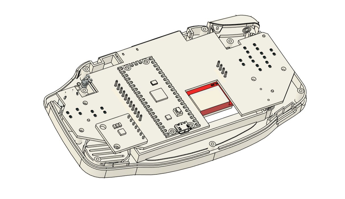
We can construct our PiBoy in this shell, but there is a minor glitch: the Game Boy Advance's PCB size. The existing PCB of the Game Boy is smaller than our PICO and other components. To create room for the new circuit, the Game Boy's battery compartment, which is located on the back end and a few pillars must be trimmed out.
- Using nipper pliers, we began the shell body edit process by removing the screw bosses on the left and right sides of the rear end.
- The AA cell holder is then fully removed; however, we must be careful not to remove the lock mechanism, which is necessary for attaching the cell cover.
- We were able to add our own circuit inside the shell by making these two adjustments, and this step ensured that there would be no space issues.
Breadboard Version
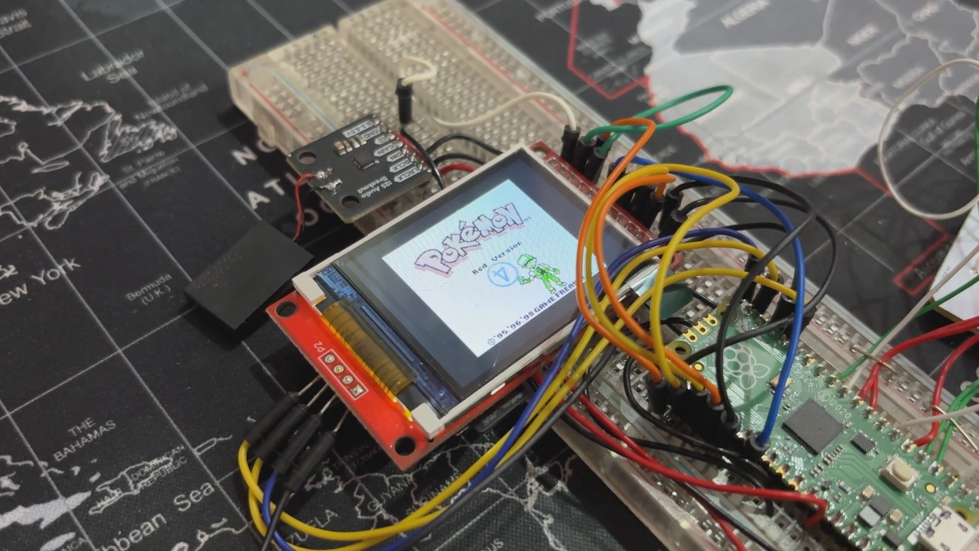
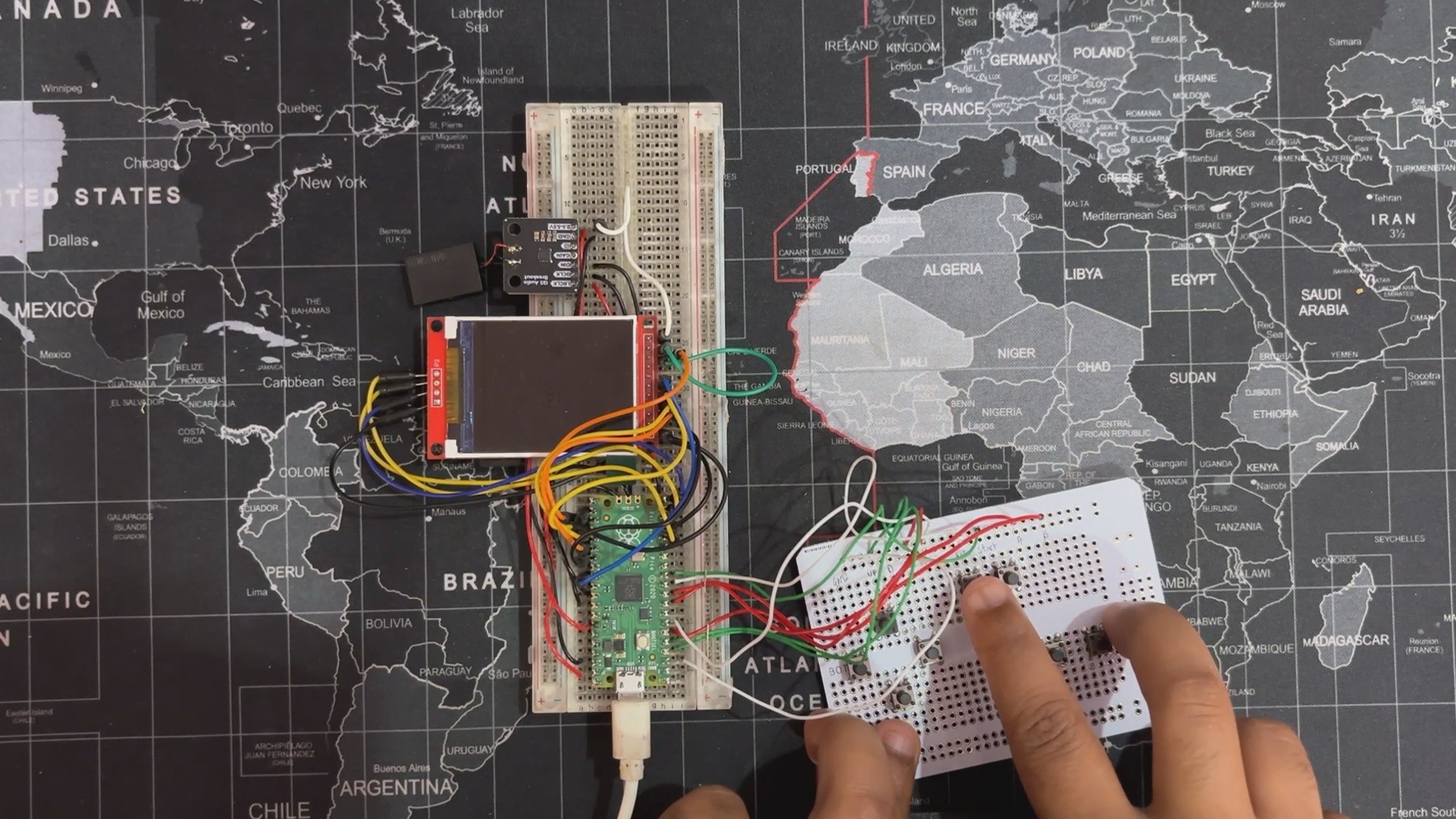
Before starting the PCB Designing process using the Pico-GB wiring scheme, I first made a complete breadboard setup. This included wiring the ILI9225 display to PICO, connecting the MAX Audio Module to PICO, and creating a button board on a perf board with eight buttons, each of which had its GPIO pin connected to PICO.
The NO Pins of each button were all connected to GND, so when a button is pressed, the GPIO attached to that button is pulled to GND, and PICO detects the button press.
The setup code was really simple: we just downloaded the uf2 file from the PICO-GB repository, pressed and held the bootsel button while connecting the USB port to PICO, and then copied and pasted the uf2 file into the PICO FLASH Storage. Re-plugging the PICO will initialize the code and cause the setup to begin working.
Game ROMs are stored on an SD card, which is connected to our PICO using the SD card breakout of the ILI9225.
After confirming that this setup is properly functioning, we move onto the next phase of this project, which is to make a custom circuit for our Game Boy Advance shell.
DESIGN
Now for the toughest part of the build—designing a custom PCB to fit the shell.
Making a PCB is pretty straightforward when you control the enclosure’s shape and dimensions. If you're designing the body from scratch, you can model everything to fit perfectly. But when you're working with a random shell, especially one without any reference files, it's a whole different story.
In my case, I picked up the shell from a local electronics market. It wasn’t an official Nintendo part, just a low-cost aftermarket version that felt a bit flimsy.
I paid around ₹800 (roughly $9.50), so I wasn’t expecting perfection, but that also meant no STEP file, no clean measurements, and a lot of guesswork. Fitting a custom circuit into that kind of housing took serious trial and error.
The modeling process kicked off with a bit of luck and a lot of manual work.
I started by searching for a 3D model of the Nintendo Game Boy Advance and surprisingly, I found one that included all the key structural details: screw bosses, ribs, lips, grids, and more. It looked promising at first, but there was a catch. While the model had accurate hole placements and component outlines, the alignment was off. If I had followed it as-is, the PCB wouldn’t have matched the shell properly.
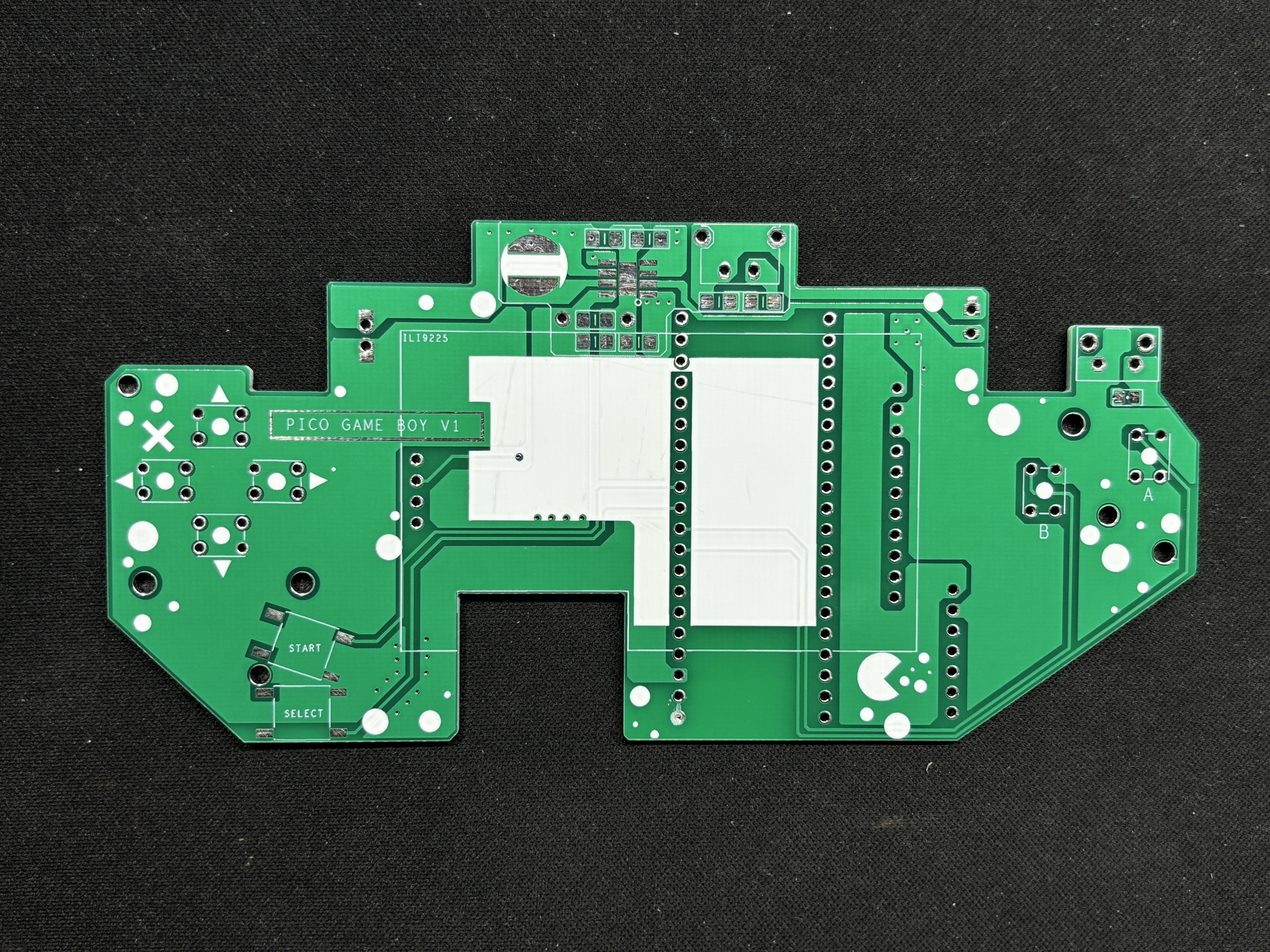
So I took the long route: manually measuring every screw boss, grid, and rib inside the shell, then correcting their positions in the 3D model. Once the geometry was dialed in, I designed a custom PCB around those mounting points. This board included push switches, the ILI9225 display, and the MAX audio module.
To validate the fit, we 3D printed the PCB and test-mounted all the components. After a few tweaks and iterations, we finally had a board that fit the shell perfectly custom-shaped and tailored specifically for this Game Boy Advance body.
PCB Design
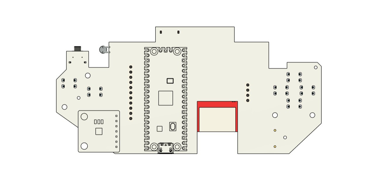
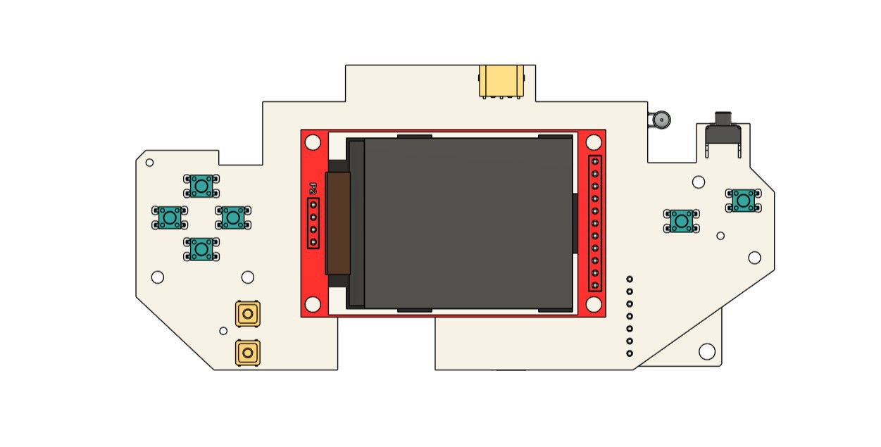
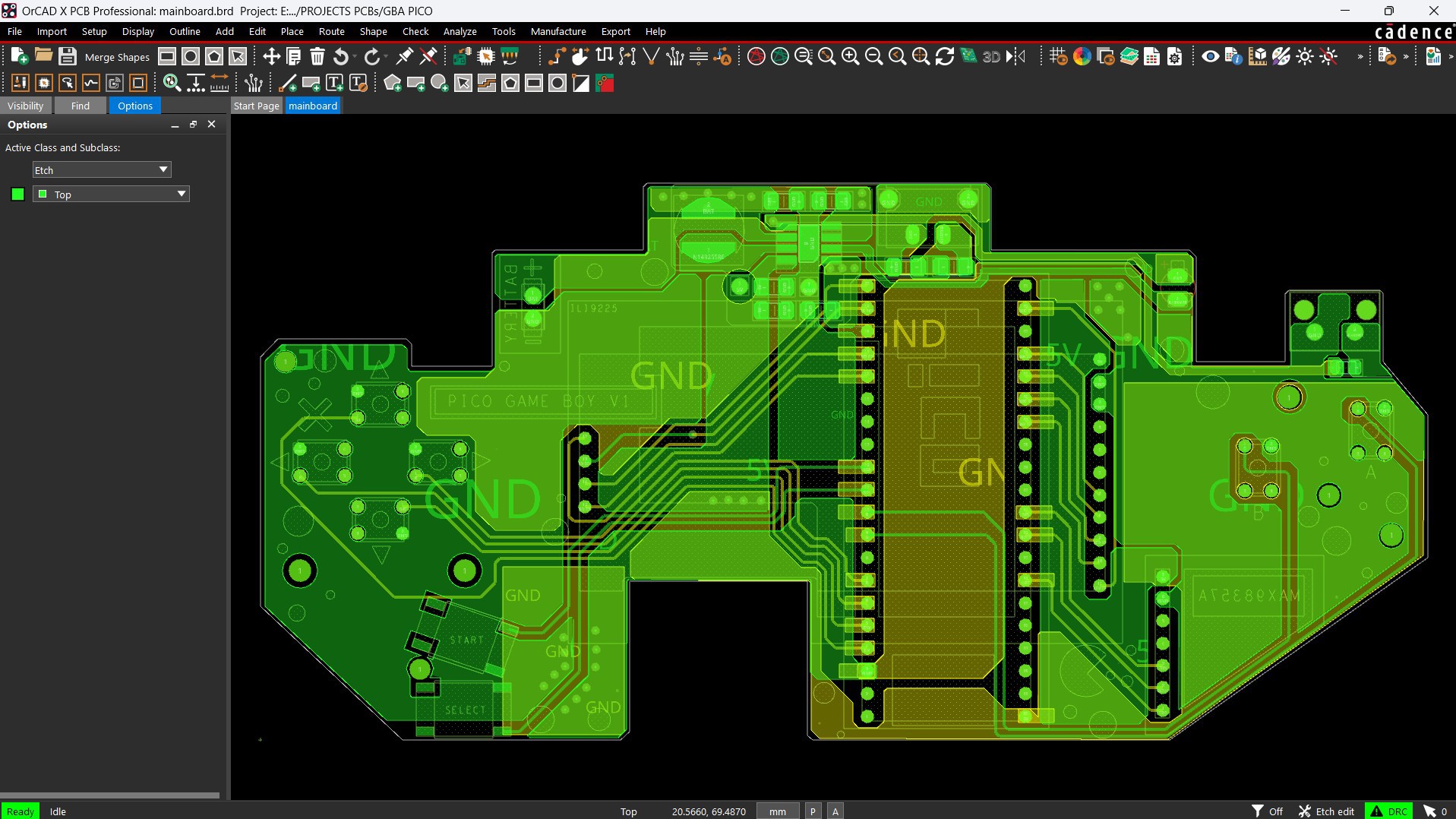
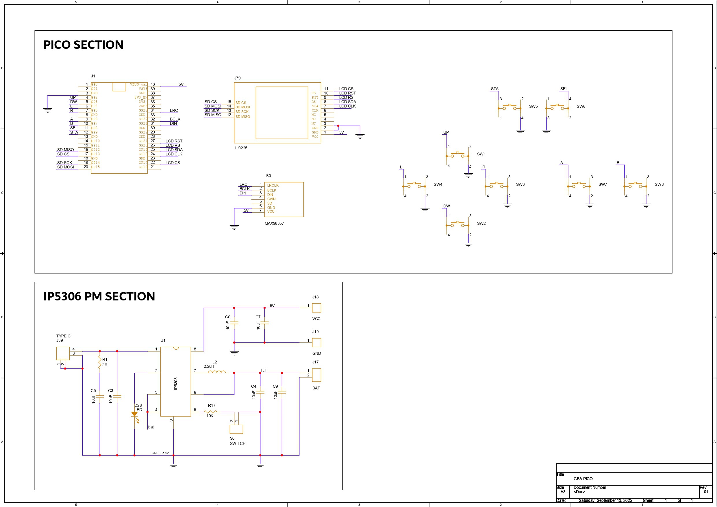
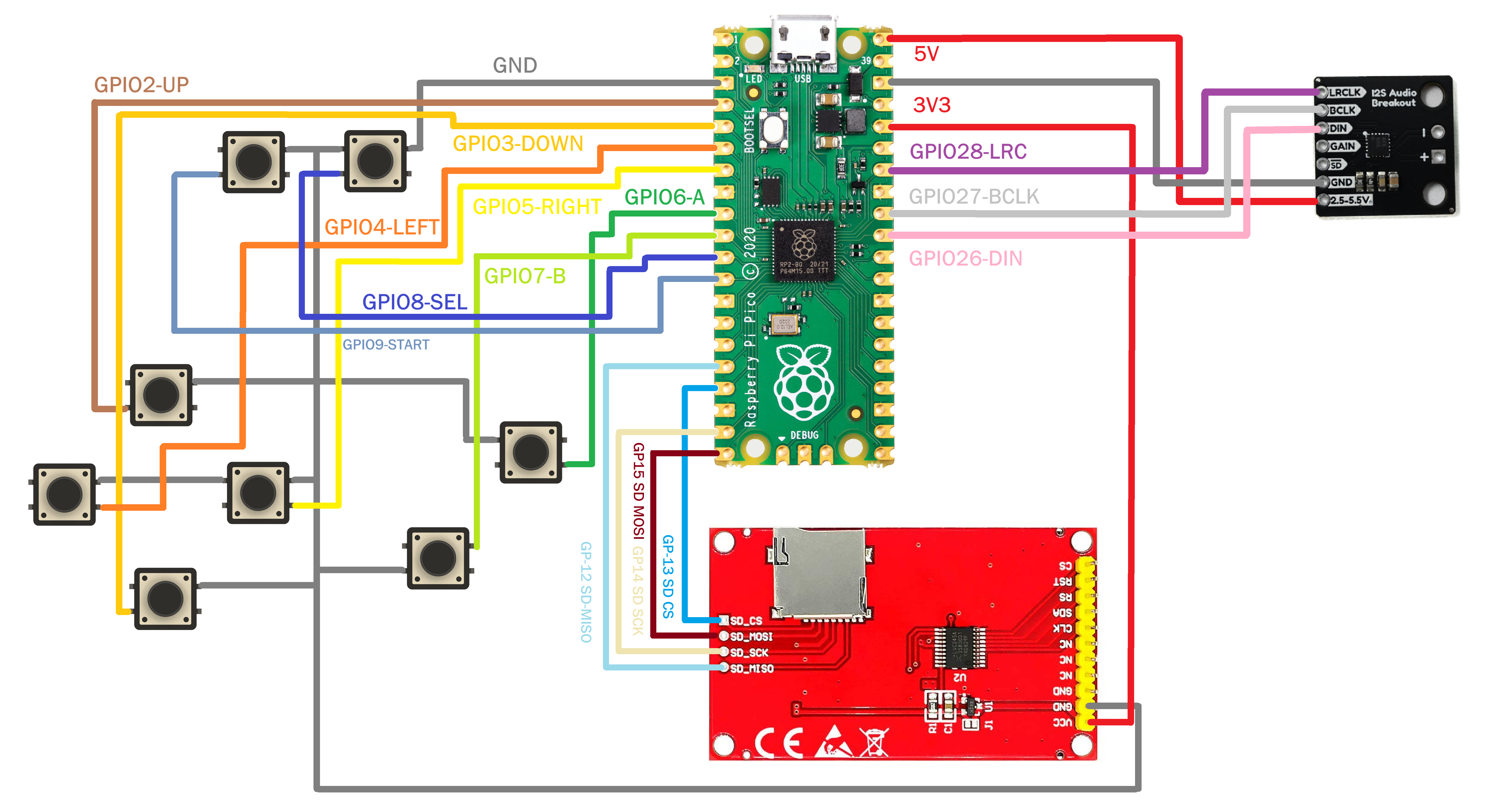
The PCB for PiBoy Advance is split into two major sections: the Pico Setup and the Peripheral Connections. At the heart of it all is the Raspberry Pi Pico, which interfaces with the ILI9225 display, the MAX98357 audio module, and a set of push buttons for user input.
We’ve made full use of the RP2040’s GPIOs to handle all button inputs:
- GPIO2 - Button Up
- GPIO3 - Button Down
- GPIO4 - Button Left
- GPIO5 - Button Right
- GPIO6 - Button A
- GPIO7 - Button B
- GPIO8 - Select
- GPIO9 - Start
The SD card slot of ILI9225 is wired for SPI communication with PICO through the following GPIOs:
- GPIO12 - MISO
- GPIO13 - CS
- GPIO14 - SCK
- GPIO15 - MOSI
- GND - Pico GND
- VCC - Pico VBUS
The Display is powered via the Pico’s 3.3V and controlled through the following GPIOs:
- VCC - 3.3V
- GPIO22 - LCD LED
- GPIO21 - RESET
- GPIO20 - RS
- GPIO19 - SDI
- GPIO18 - CLK
- GPIO17 - LCD CS
The audio module is powered by VBUS and connected as follows:
- VCC - Pico VBUS
- GND - Pico GND
- GPIO28 - LRC
- GPIO27 - BCLK
- GPIO26 - DIN
The second major section of the PCB design focuses on power management—an essential part of any handheld device.
For the PiBoy Advance, we chose a single-cell LiPo battery as the power source, charged via a USB Type-C port. To handle power regulation, we integrated the IP5306, a compact power management IC capable of delivering a stable 5V at up to 2A from a 3.7V Li-ion or LiPo cell.
The IP5306’s output is routed directly to the VBUS pin of the Raspberry Pi Pico, which in turn powers the display, the Pico itself, and all other components on the board. It’s a clean, centralized setup that keeps the system efficient and compact.
This IC also includes smart features like low-cut and high-cut protection and a battery fuel indicator LED. During charging, the LED blinks slowly and becomes solid once the battery is fully charged. When the battery is low, it blinks rapidly every two seconds—making it easy to monitor power status without extra circuitry.
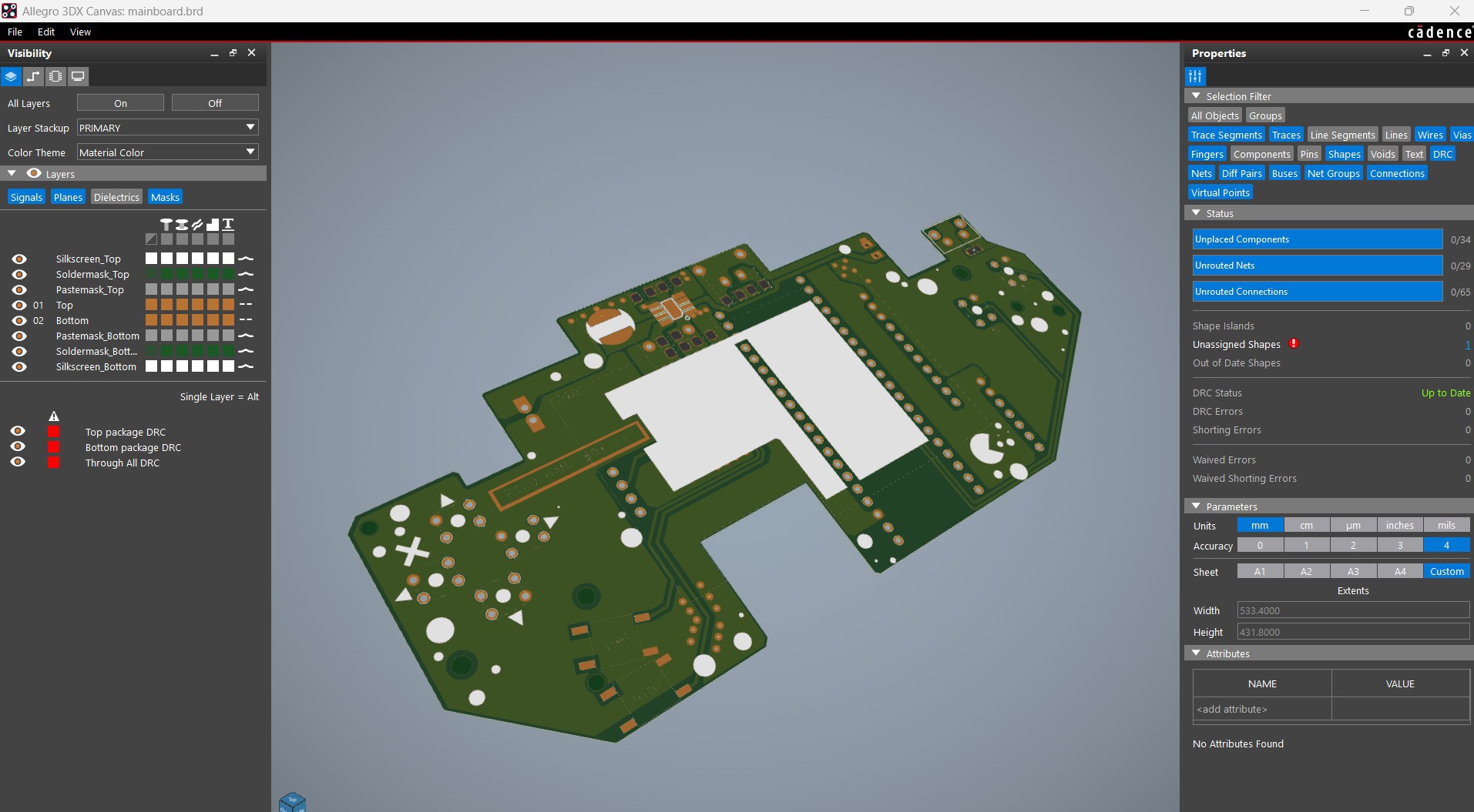
Once the schematic was finalized, we moved on to the PCB layout. The board outline shape was based on the shell dimensions, and component placement was guided by the 3D model.
The top side of the PCB houses all SMD components, including the display and push buttons, while the bottom side holds the Raspberry Pi Pico, battery terminals, and the MAX98357 audio module.
NextPCB PCB Service
After completing the PCB design, Gerber data was sent to HQ NextPCB, and an order was placed for a Green solder mask with white silkscreen.
After placing the order, the PCBs were received within a week, and the PCB quality was pretty great.
In addition, I have to bring in HQDFM to you, which helped me a lot through many projects. Huaqiu’s in-house engineers developed the free Design for Manufacturing software, HQDFM, revolutionizing how PCB designers visualize and verify their designs.
Take advantage of NextPCB's Accelerator campaign and get 2 free assembled RP2040-based PCBs for your innovative projects.
https://www.nextpcb.com/blog/rp2040-free-pcba-prototypes-nextpcb-accelerator
This offer covers all costs, including logistics, making it easier and more affordable to bring your ideas to life. SMT services can be expensive, but NextPCB is here to help you overcome that hurdle. Simply share your relevant project, and they'll take care of the rest. Don't miss out on this amazing opportunity to advance your tech creations!
HQDFM: Free Online Gerber Viewer and DFM Analysis Tool
Also, NextPCB has its own Gerber Viewer and DFM analysis software.
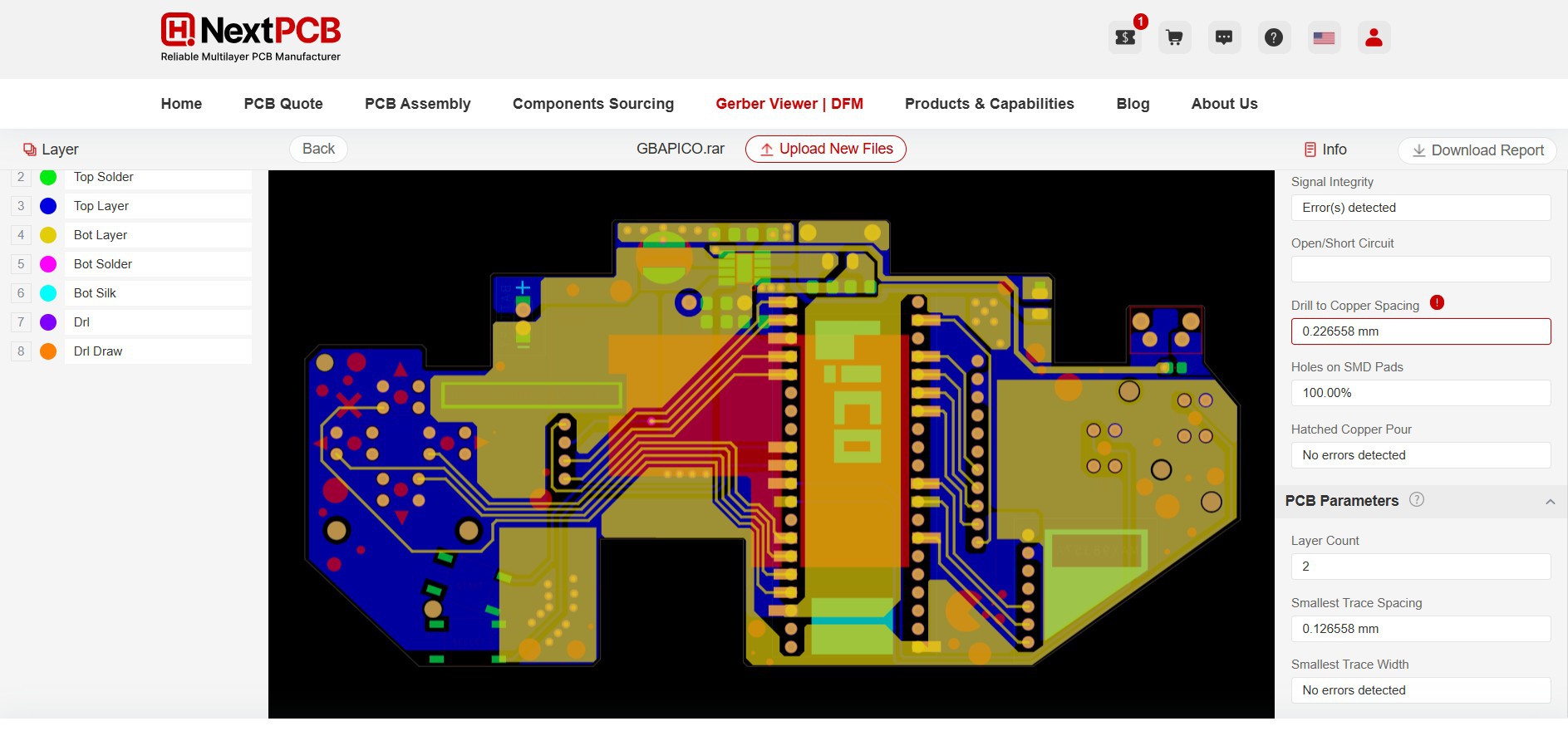
Your designs are improved by their HQDFM software (DFM) services. Since I find it annoying to have to wait around for DFM reports from manufacturers, HQDFM is the most efficient method for performing a pre-event self-check.
This is what I see in the online Gerber Viewer. It's decent for a quick look, but not entirely clear. For full functionality—like detailed DFM analysis for PCBA—you’ll need to download the desktop software. The web version only offers a basic DFM report.
With comprehensive Design for Manufacture (DFM) analysis features, HQDFM is a free, sophisticated online PCB Gerber file viewer.
With over 15 years of industry experience, it offers valuable insights into advanced manufacturing processes. If you’re looking for reliable PCB services at a budget-friendly price, HQ NextPCB is definitely worth checking out.