 Bertrand Selva
This log presents the first attempt at implementing a full computation chain based on the Residue Number System (RNS) on an FPGA—specifically, a Cyclone IV. Division is systematically avoided in favor of additions, bit shifts, and lookup tables. The complete pipeline, from conversion to reconstruction, is justified step by step. The code is available on my github : https://github.com/Bertrand-selvasystems/RNS-on-FPGA/.
Hardware and development environment
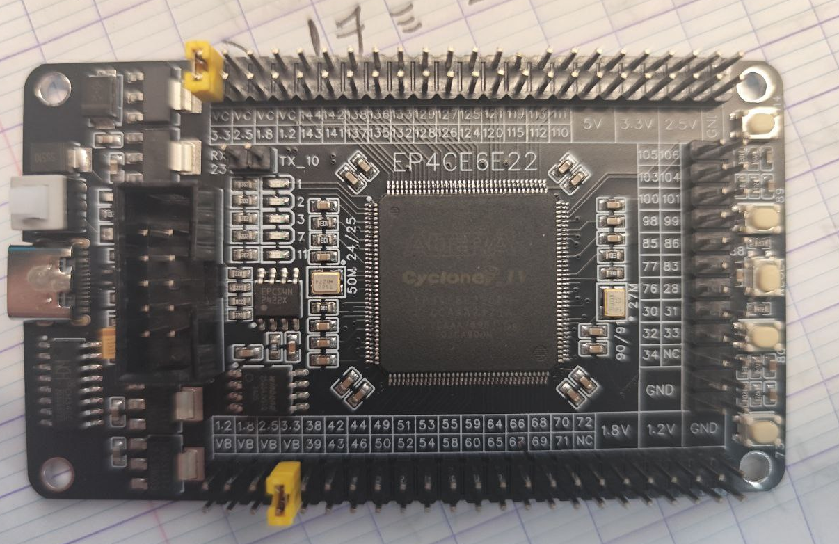
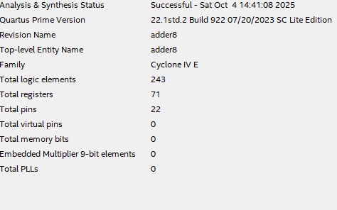
The hardware target is a Cyclone IV FPGA (EP4CE family). Physical programming will be performed later, as soon as the programmer arrives (ordered from Aliexpress, this will take a few more days). At this stage, the entire approach is based on software simulation using Quartus Prime Lite for synthesis, and Questa Intel FPGA (Starter Edition) for timing and functional simulation.
This is the FPGA software suite that appears the most accessible and best documented. However, you must request a .dat license file from Intel, even for the free "starter" version.
Some demonstrations for RNS
I wanted to review all the calculations necessary for the determination of the different moduli. This is very simple as soon as you know the following properties, which can be rigorously demonstrated from the very definition of the remainder in Euclidean division.
Let a and b be two integers, and q a modulus:
- a = na × q + ra, with 0 ≤ ra < q
- b = nb × q + rb, with 0 ≤ rb < q
Addition:
(a + b) = (nₐq + rₐ) + (n_bq + r_b) = (nₐ + n_b)q + (rₐ + r_b)
The remainder modulo q is thus (a + b) mod q = (rₐ + r_b) mod q.
Multiplication:
(a × b) = (nₐq + rₐ)(n_bq + r_b)
        = [nₐ n_b q² + (nₐ r_b + n_b rₐ)q + rₐ r_b]
Modulo q, only the rₐ r_b terms remain: (a × b) mod q = (rₐ × r_b) mod q.
Subtraction:
(a - b) = (nₐq + rₐ) - (n_bq + r_b) = (nₐ - n_b)q + (rₐ - r_b)
The remainder is (rₐ - r_b + q) mod q, with the addition of q ensuring a positive result.
These relations are used for the calculation of the residues of different moduli, and can be written as ri or i mod n...
Binary → RNS conversion without divisions
Use of nibbles: motivation and generalization
A byte is naturally structured in two 4-bit parts, called “nibbles”: the high nibble (H = x[7:4]) and the low nibble (L = x[3:0]). This binary representation is standard in digital architectures, as it allows the byte to be factored as:
x = 16 × H + L
The advantage of this decomposition is that it optimizes arithmetic operations, in particular for modulo conversion, thanks to the modular structure of 16 in most common bases. The use of nibbles, universal in digital electronics, thus allows combinatorial logic to be optimized.
Modulo 5 conversion
We first express 16 modulo 5:
16 = 3 × 5 + 1, so 16 ≡ 1 (mod 5)
It follows that:
x mod 5 = (16H + L) mod 5
x mod 5 = (((H mod 5)*(16 mod 5)) mod 5 + L mod 5) mod 5
x mod 5 = (((H mod 5)*1) mod 5 + L mod 5) mod 5
x mod 5 = (r_H + r_L) mod 5
With
(a + b) mod q = (rₐ + r_b) mod q.
Thus:
x mod 5 = (H + L) mod 5
In other words, the remainder of the division by 5 is obtained simply by summing the two nibbles and applying a reduction modulo 5. This is performed with a short addition (max 5 bits) followed by a lookup table (LUT) to bring the sum into the 0..4 interval.
function [2:0] mod5_nibble;
  input [3:0] h, l;
  begin
    mod5_nibble = lut_sum_mod5(h + l); // LUT over [0..30]
  end
endfunction
Modulo 7 conversion
We use the relation:
16 = 2 × 7 + 2, so 16 ≡ 2 (mod 7)
So: x mod 7 = (2H + L) mod 7.
The calculation of 2H is done by a simple left shift (bit-shift), then the low nibble is added and a modulo 7 reduction is applied via a LUT.
Modulo 9 conversion
Here, 16 = 1 × 9 + 7, so 16 ≡ 7 (mod 9).
Thus: x mod 9 = (7H + L) mod 9.
Long multiplication is avoided: 7H = (4H + 2H + H), i.e., two left shifts and an addition.
function [3:0] mod9_nibble;
  input [3:0] h, l;
  reg [6:0] s;
  begin
    s = (h << 2) + (h << 1) + h + l;
    mod9_nibble = lut_sum_mod9(s);
  end
endfunction
Optimization note: In all cases, the conversion consists of adding small-width values, then using a small lookup table. On FPGA, this translates to:
- Additions with small fan-in, no global carry propagation (fast, low-cost logic)
- Bit shifts (almost free)
- Very small LUTs perfectly matched to FPGA resources
Thus, binary→RNS conversion does not penalize the operating frequency and uses little logic resources, at least in the case of a small number of moduli.
Operation in RNS domain
In the RNS system, each operation is performed locally, for each residue. In this experiment, the operation chosen is addition of 2 to each modulus, that is: for each modulus, r → (r + 2) mod m.
This choice may seem a bit silly (a lot of machinery just to perform a +2), but it allows controlled verification of the entire pipeline, including the validity of the round-trip conversions and information preservation. It's a good starting point.
function [2:0] add5_2; input [2:0] a; reg [3:0] t; begin
  t = {1'b0,a} + 4'd2; if (t >= 4'd5) t = t - 4'd5; add5_2 = t[2:0];
end endfunction
// Same scheme for mod 7 and mod 9.
Benefit: to validate the correctness of the entire pipeline, from binary to RNS and back, on an operation whose result is predictable and controllable. See the last section with the simulation results and code: It works!
RNS → binary (CRT) without divisions
CRT statement
For coprime moduli {m1, m2, ..., mk} with total product M = ∏ mi,
the Chinese Remainder Theorem (CRT) states that any system of residues (r1, r2, ..., rk) corresponds to a unique integer x ∈ [0, M-1] such that:
x ≡ ri (mod mi) for all i
The explicit reconstruction formula is:
x = Σi=1..k [ri × Mi × yi] mod M
with Mi = M / mi, and yi the multiplicative inverse of Mi modulo mi.
In our example:
- {5, 7, 9}, M = 315
- M₅ = 63, M₇ = 45, M₉ = 35
- y₅ = 2, y₇ = 5, y₉ = 8
- We use the products Ki = Mi × yi as coefficients.
S = K5 * r5 + K7 * r7 + K9 * r9;
Numerical values: K₅ = 126, K₇ = 225, K₉ = 280.
Here is the code corresponding to the LUT definitions:
// mini-ROM Ai*ri (M=315)
  function [11:0] T5; input [2:0] r; begin
    case (r)
      3'd0: T5=12'd0;   3'd1: T5=12'd126; 3'd2: T5=12'd252;
      3'd3: T5=12'd378; 3'd4: T5=12'd504; default: T5=12'd0;
    endcase
  end endfunction
  function [11:0] T7; input [2:0] r; begin
    case (r)
      3'd0: T7=12'd0;   3'd1: T7=12'd225; 3'd2: T7=12'd450;
      3'd3: T7=12'd675; 3'd4: T7=12'd900; 3'd5: T7=12'd1125;
      3'd6: T7=12'd1350; default: T7=12'd0;
    endcase
  end endfunction
  function [11:0] T9; input [3:0] r; begin
    case (r)
      4'd0: T9=12'd0;   4'd1: T9=12'd280; 4'd2: T9=12'd560;
      4'd3: T9=12'd840; 4'd4: T9=12'd1120;4'd5: T9=12'd1400;
      4'd6: T9=12'd1680;4'd7: T9=12'd1960;4'd8: T9=12'd2240;
      default: T9=12'd0;
    endcase
  end endfunction
Modulo 315 reduction without division
To obtain a result bounded in [0,314], the reduction modulo 315 is performed without division, by conditional subtractions:
Proceed as follows:
- As long as the intermediate value is greater than or equal to 2520 (8 × 315), subtract 2520
- If the result remains greater than or equal to 1260 (4 × 315), subtract 1260
- If still greater than or equal to 630 (2 × 315), subtract 630
- If greater than or equal to 315, subtract 315
- The remaining value then belongs to [0,314]
Each subtraction eliminates a block of 315 (or a multiple). This purely combinatorial strategy avoids the high cost of integer division and fits perfectly with FPGA architectures; it can be generalized to larger moduli.
ref : Piestrak, S.J., “Design of Residue Generators and Multi-Operand Modular Adders Using Carry-Save Adders,”
function [8:0] reduce315;
  input [11:0] val;
  reg [11:0] t;
begin
  t = val;
  if (t >= 12'd2520) t = t - 12'd2520;
  if (t >= 12'd1260) t = t - 12'd1260;
  if (t >= 12'd630 ) t = t - 12'd630;
  if (t >= 12'd315 ) t = t - 12'd315;
  reduce315 = t[8:0];
end endfunction
Synthesis and perspectives
The presented architecture leverages the granularity of the FPGA: each addition, shift, or LUT is mapped onto an elementary logic unit, with minimal pipeline depth. The maximum achievable frequency then depends directly on the propagation delay in these logics.
For simple operations (addition of small integers, LUT), these propagation delays are particularly short, allowing high operating frequencies, often limited only by the critical path.
On FPGA, the general optimization strategy is to favor the use of local combinatorial resources, to limit carry propagation, and to break down operations into well-synchronized sequential phases. This philosophy allows an optimal compromise between frequency, logic occupancy, and power consumption.
Applying RNS to this type of pipeline demonstrates that even conversion operations requiring division can be broken down into simpler independent sub-operations.
Furthermore, RNS allows the core computation to be performed on each modulus independently. For example, our current phase 3 (+2) is executed on each modulus independently. All calculations can therefore be performed in parallel without interdependence, paving the way for large-scale processing on simple, efficient hardware architectures. It is somewhat as if we could rigorously process, for a large number, the units, tens, hundreds, thousands, etc., completely independently...
Project perspectives
This is a first stone thrown into the pond. I will consolidate this initial code as follows in the coming logs:
- Extension to 16 bits: by increasing the data width and the set of modules (for example {7, 11, 13, 15, 17, 19, 23, 29, 31}), while maintaining the simplicity of conversions thanks to the nibble + LUT architecture.
- Complete FIR pipeline: replacing the elementary operation (+2) by a complete FIR chain (finite impulse response filter) entirely in RNS allows the exploration of massively parallel processing capabilities—a domain where RNS truly shines (and the reason it was used in the Duga K340 computer).
- Accurate resource and frequency measurements: the goal is to objectively quantify logic occupancy, maximum frequency, and actual consumption, to support comparisons and guide implementation choices.
- Real deployment via fast interface: integration between the FPGA and a microcontroller (ESP32), for example via I2S "LCD", allows validation of real-world operation and evaluation of the system's sustainable throughput.
Your comments and technical feedback are welcome: this work is very exploratory and any help or opinion from a pro is much appreciated...
Summary project
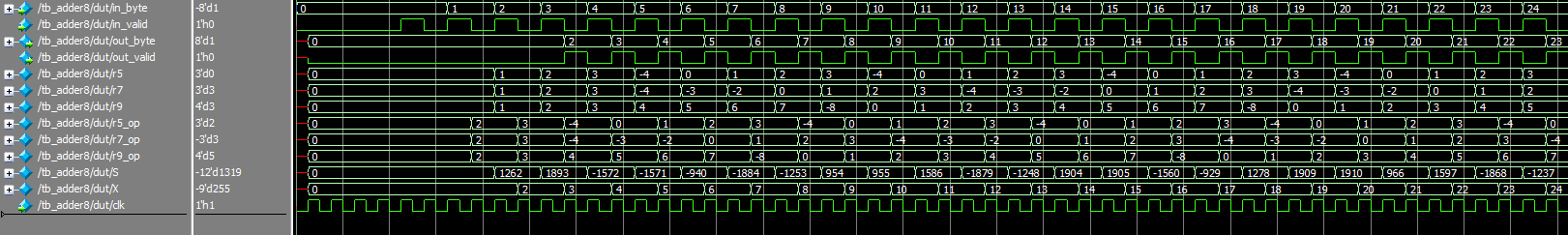 The pipeline operates exactly as expected!
 Each clock edge triggers the orderly propagation of operands through the intermediate registers (r5, r7, r9, etc.).
The signals out_valid and out_byte stabilize after two cycles, and the +2 operation works as intended.
A small victory already...
Code
`timescale 1ns/1ps
`default_nettype none

module adder8 (
  input  wire        clk,
  input  wire        rst_n,

  // Bus entrée
  input  wire [7:0]  in_byte,
  input  wire        in_valid,
  output wire        in_ready,

  // Bus sortie
  output reg  [7:0]  out_byte,
  output reg         out_valid,
  input  wire        out_ready
);

  // ====================================================
  // Phase 1 — Capture entrée
  // ====================================================
  reg  [7:0] x0;
  reg        v0;

  wire s1_ready = 1'b1;
  assign in_ready = (~v0) | s1_ready;

  always @(posedge clk) begin
    if (!rst_n) begin
      v0 <= 1'b0;
      x0 <= 8'd0;
    end else begin
      if (in_ready) begin
        v0 <= in_valid;
        if (in_valid) x0 <= in_byte;
      end
    end
  end

  // ====================================================
  // Phase 2 — Binaire -> RNS (5,7,9) via nibbles + LUT
  // ====================================================


  reg        v1;
  reg  [2:0] r5;
  reg  [2:0] r7;
  reg  [3:0] r9;

  wire [3:0] H = x0[7:4];
  wire [3:0] L = x0[3:0];


// --- MOD 5 : (H+L) mod 5 ---
// S = H+L est sur 5 bits (0..30)
function [2:0] lut_sum_mod5;
  input [4:0] s;
  begin
    case (s)
      5'd0:  lut_sum_mod5=3'd0;  5'd1:  lut_sum_mod5=3'd1;  5'd2:  lut_sum_mod5=3'd2;  5'd3:  lut_sum_mod5=3'd3;  5'd4:  lut_sum_mod5=3'd4;
      5'd5:  lut_sum_mod5=3'd0;  5'd6:  lut_sum_mod5=3'd1;  5'd7:  lut_sum_mod5=3'd2;  5'd8:  lut_sum_mod5=3'd3;  5'd9:  lut_sum_mod5=3'd4;
      5'd10: lut_sum_mod5=3'd0;  5'd11: lut_sum_mod5=3'd1;  5'd12: lut_sum_mod5=3'd2;  5'd13: lut_sum_mod5=3'd3;  5'd14: lut_sum_mod5=3'd4;
      5'd15: lut_sum_mod5=3'd0;  5'd16: lut_sum_mod5=3'd1;  5'd17: lut_sum_mod5=3'd2;  5'd18: lut_sum_mod5=3'd3;  5'd19: lut_sum_mod5=3'd4;
      5'd20: lut_sum_mod5=3'd0;  5'd21: lut_sum_mod5=3'd1;  5'd22: lut_sum_mod5=3'd2;  5'd23: lut_sum_mod5=3'd3;  5'd24: lut_sum_mod5=3'd4;
      5'd25: lut_sum_mod5=3'd0;  5'd26: lut_sum_mod5=3'd1;  5'd27: lut_sum_mod5=3'd2;  5'd28: lut_sum_mod5=3'd3;  5'd29: lut_sum_mod5=3'd4;
      5'd30: lut_sum_mod5=3'd0;
    endcase
  end
endfunction

function [2:0] mod5_nibble;
  input [3:0] h,l;
  begin
    mod5_nibble = lut_sum_mod5(h + l);  // direct LUT
  end
endfunction


// --- MOD 7 direct : (2H+L) % 7
// S = 2H + L va de 0..45
function [2:0] lut_sum_mod7;
  input [5:0] s;
  begin
    case (s)
      6'd0: lut_sum_mod7=3'd0;   6'd1: lut_sum_mod7=3'd1;   6'd2: lut_sum_mod7=3'd2;   6'd3: lut_sum_mod7=3'd3;
      6'd4: lut_sum_mod7=3'd4;   6'd5: lut_sum_mod7=3'd5;   6'd6: lut_sum_mod7=3'd6;   6'd7: lut_sum_mod7=3'd0;
      6'd8: lut_sum_mod7=3'd1;   6'd9: lut_sum_mod7=3'd2;   6'd10:lut_sum_mod7=3'd3;   6'd11:lut_sum_mod7=3'd4;
      6'd12:lut_sum_mod7=3'd5;   6'd13:lut_sum_mod7=3'd6;   6'd14:lut_sum_mod7=3'd0;   6'd15:lut_sum_mod7=3'd1;
      6'd16:lut_sum_mod7=3'd2;   6'd17:lut_sum_mod7=3'd3;   6'd18:lut_sum_mod7=3'd4;   6'd19:lut_sum_mod7=3'd5;
      6'd20:lut_sum_mod7=3'd6;   6'd21:lut_sum_mod7=3'd0;   6'd22:lut_sum_mod7=3'd1;   6'd23:lut_sum_mod7=3'd2;
      6'd24:lut_sum_mod7=3'd3;   6'd25:lut_sum_mod7=3'd4;   6'd26:lut_sum_mod7=3'd5;   6'd27:lut_sum_mod7=3'd6;
      6'd28:lut_sum_mod7=3'd0;   6'd29:lut_sum_mod7=3'd1;   6'd30:lut_sum_mod7=3'd2;   6'd31:lut_sum_mod7=3'd3;
      6'd32:lut_sum_mod7=3'd4;   6'd33:lut_sum_mod7=3'd5;   6'd34:lut_sum_mod7=3'd6;   6'd35:lut_sum_mod7=3'd0;
      6'd36:lut_sum_mod7=3'd1;   6'd37:lut_sum_mod7=3'd2;   6'd38:lut_sum_mod7=3'd3;   6'd39:lut_sum_mod7=3'd4;
      6'd40:lut_sum_mod7=3'd5;   6'd41:lut_sum_mod7=3'd6;   6'd42:lut_sum_mod7=3'd0;   6'd43:lut_sum_mod7=3'd1;
      6'd44:lut_sum_mod7=3'd2;   6'd45:lut_sum_mod7=3'd3;
      default: lut_sum_mod7=3'd0;
    endcase
  end
endfunction

function [2:0] mod7_nibble;
  input [3:0] h,l;
  begin
    mod7_nibble = lut_sum_mod7((h << 1) + l);  // s = 2H + L
  end
endfunction

// --- MOD 9 : (7H + L) % 9 ---
// s = 7H + L ∈ [0..120]. LUT directe sur s.
function [3:0] lut_sum_mod9;
  input [6:0] s;
  begin
    case (s)
      // s % 9 == 0
      7'd0,  7'd9,  7'd18, 7'd27, 7'd36, 7'd45, 7'd54, 7'd63, 7'd72, 7'd81, 7'd90, 7'd99, 7'd108, 7'd117:
        lut_sum_mod9 = 4'd0;
      // s % 9 == 1
      7'd1,  7'd10, 7'd19, 7'd28, 7'd37, 7'd46, 7'd55, 7'd64, 7'd73, 7'd82, 7'd91, 7'd100, 7'd109, 7'd118:
        lut_sum_mod9 = 4'd1;
      // s % 9 == 2
      7'd2,  7'd11, 7'd20, 7'd29, 7'd38, 7'd47, 7'd56, 7'd65, 7'd74, 7'd83, 7'd92, 7'd101, 7'd110, 7'd119:
        lut_sum_mod9 = 4'd2;
      // s % 9 == 3
      7'd3,  7'd12, 7'd21, 7'd30, 7'd39, 7'd48, 7'd57, 7'd66, 7'd75, 7'd84, 7'd93, 7'd102, 7'd111, 7'd120:
        lut_sum_mod9 = 4'd3;
      // s % 9 == 4
      7'd4,  7'd13, 7'd22, 7'd31, 7'd40, 7'd49, 7'd58, 7'd67, 7'd76, 7'd85, 7'd94, 7'd103, 7'd112:
        lut_sum_mod9 = 4'd4;
      // s % 9 == 5
      7'd5,  7'd14, 7'd23, 7'd32, 7'd41, 7'd50, 7'd59, 7'd68, 7'd77, 7'd86, 7'd95, 7'd104, 7'd113:
        lut_sum_mod9 = 4'd5;
      // s % 9 == 6
      7'd6,  7'd15, 7'd24, 7'd33, 7'd42, 7'd51, 7'd60, 7'd69, 7'd78, 7'd87, 7'd96, 7'd105, 7'd114:
        lut_sum_mod9 = 4'd6;
      // s % 9 == 7
      7'd7,  7'd16, 7'd25, 7'd34, 7'd43, 7'd52, 7'd61, 7'd70, 7'd79, 7'd88, 7'd97, 7'd106, 7'd115:
        lut_sum_mod9 = 4'd7;
      // s % 9 == 8
      7'd8,  7'd17, 7'd26, 7'd35, 7'd44, 7'd53, 7'd62, 7'd71, 7'd80, 7'd89, 7'd98, 7'd107, 7'd116:
        lut_sum_mod9 = 4'd8;

      default: lut_sum_mod9 = 4'd0; // sécurité
    endcase
  end
endfunction

function [3:0] mod9_nibble;
  input [3:0] h, l;
  reg  [6:0] s; // 0..120
  begin
    // 7H = 4H + 2H + H (pas de multiplieur)
    s = (h << 2) + (h << 1) + h + l;
    mod9_nibble = lut_sum_mod9(s);
  end
endfunction


  always @(posedge clk) begin
    if (!rst_n) begin
      v1 <= 1'b0; r5 <= 3'd0; r7 <= 3'd0; r9 <= 4'd0;
    end else begin
      v1 <= v0;
      if (v0) begin
        r5 <= mod5_nibble(H, L);
        r7 <= mod7_nibble(H, L);
        r9 <= mod9_nibble(H, L);
      end
    end
  end

  // ====================================================
  // Phase 3 — Opération (+2) en RNS
  // ====================================================
  reg        v2;
  reg  [2:0] r5_op, r7_op;
  reg  [3:0] r9_op;

  function [2:0] add5_2; input [2:0] a; reg [3:0] t; begin
    t = {1'b0,a} + 4'd2; if (t >= 4'd5) t = t - 4'd5; add5_2 = t[2:0];
  end endfunction
  function [2:0] add7_2; input [2:0] a; reg [3:0] t; begin
    t = {1'b0,a} + 4'd2; if (t >= 4'd7) t = t - 4'd7; add7_2 = t[2:0];
  end endfunction
  function [3:0] add9_2; input [3:0] a; reg [4:0] t; begin
    t = {1'b0,a} + 5'd2; if (t >= 5'd9) t = t - 5'd9; add9_2 = t[3:0];
  end endfunction

  always @(posedge clk) begin
    if (!rst_n) begin
      v2 <= 1'b0; r5_op <= 3'd0; r7_op <= 3'd0; r9_op <= 4'd0;
    end else begin
      v2 <= v1;
      if (v1) begin
        r5_op <= add5_2(r5);
        r7_op <= add7_2(r7);
        r9_op <= add9_2(r9);
      end
    end
  end

  // ====================================================
  // Phase 4 — CRT (RNS -> binaire)
  // ====================================================
  // mini-ROM Ai*ri (M=315)
  function [11:0] T5; input [2:0] r; begin
    case (r)
      3'd0: T5=12'd0;   3'd1: T5=12'd126; 3'd2: T5=12'd252;
      3'd3: T5=12'd378; 3'd4: T5=12'd504; default: T5=12'd0;
    endcase
  end endfunction
  function [11:0] T7; input [2:0] r; begin
    case (r)
      3'd0: T7=12'd0;   3'd1: T7=12'd225; 3'd2: T7=12'd450;
      3'd3: T7=12'd675; 3'd4: T7=12'd900; 3'd5: T7=12'd1125;
      3'd6: T7=12'd1350; default: T7=12'd0;
    endcase
  end endfunction
  function [11:0] T9; input [3:0] r; begin
    case (r)
      4'd0: T9=12'd0;   4'd1: T9=12'd280; 4'd2: T9=12'd560;
      4'd3: T9=12'd840; 4'd4: T9=12'd1120;4'd5: T9=12'd1400;
      4'd6: T9=12'd1680;4'd7: T9=12'd1960;4'd8: T9=12'd2240;
      default: T9=12'd0;
    endcase
  end endfunction

  reg        v3, v4;
  reg [11:0] S;
  reg  [8:0] X;   // debug
  reg  [7:0] y4;

  function [8:0] reduce315;
    input [11:0] val;
    reg   [11:0] t;
  begin
    t = val;
    if (t >= 12'd2520) t = t - 12'd2520;
    if (t >= 12'd1260) t = t - 12'd1260;
    if (t >= 12'd630 ) t = t - 12'd630;
    if (t >= 12'd315 ) t = t - 12'd315;
    reduce315 = t[8:0];
  end endfunction

  wire [8:0] S_red = reduce315(S);

  always @(posedge clk) begin
    if (!rst_n) begin
      v3 <= 1'b0; v4 <= 1'b0; S <= 12'd0; X <= 9'd0; y4 <= 8'd0;
    end else begin
      v3 <= v2;
      if (v2) S <= T5(r5_op) + T7(r7_op) + T9(r9_op);

      v4 <= v3;
      if (v3) begin
        X  <= S_red;        // debug
        y4 <= S_red[7:0];   // aligné avec v4
      end
    end
  end

  // ====================================================
  // Phase 5 — buffer de sortie
  // ====================================================
  reg  [7:0] y5;
  reg        v5;

  wire s5_ready = (~v5) | out_ready;

  always @(posedge clk) begin
    if (!rst_n) begin
      v5 <= 1'b0; y5 <= 8'd0; out_valid <= 1'b0; out_byte <= 8'd0;
    end else begin
      if (s5_ready) begin
        v5 <= v4;
        if (v4) y5 <= y4;
      end
      out_valid <= v5;
      out_byte  <= y5;
    end
  end

endmodule

`default_nettype wire
Discussions
Become a Hackaday.io Member
Create an account to leave a comment. Already have an account? Log In.