 Bertrand Selva
This marks one of the key milestones towards the final objective: a design that performs +2, but this time using all 9 moduli, allowing for a dynamic range of 237.
Input data arrives via an 8-bit bus, in two cycles per word, while output data is mapped to 16 pins.
You can find the program on my github : https://github.com/Bertrand-selvasystems/rns-pipeline-16bit
Program Details (What Changed)
Data Capture, Phase 1
Input data enters the FPGA over an 8-bit bus. On each cycle, we alternately load the low and high bytes: the first byte received (LSB) is stored temporarily, then the next one (MSB) completes the 16-bit word. As soon as the word is complete, a one-cycle validity pulse (v0) is issued to signal "word ready" for the next pipeline phase.
This simple handshake (in_fire = in_valid & in_ready, with in_ready = rst_n) ensures the input is always ready (except during reset), simplifying both testbenches and real use.
// Phase 1 — Capture 16b from 8b bus (LSB then MSB)
reg  [7:0]  x_lo;
reg         have_lo;     // 1 = LSB already captured
reg         v0;          // 1-cycle pulse: 16b word ready
reg  [15:0] x0_16;

wire in_fire = in_valid & in_ready;
assign in_ready = rst_n;

always @(posedge clk) begin
  if (!rst_n) begin
    have_lo <= 1'b0;
    v0      <= 1'b0;
    x_lo    <= 8'd0;
    x0_16   <= 16'd0;
  end else begin
    v0 <= 1'b0; // default: no pulse
    if (in_fire) begin
      if (!have_lo) begin
        // First byte: LSB
        x_lo    <= in_byte;
        have_lo <= 1'b1;
      end else begin
        // Second byte: MSB -> complete word + v0 pulse
        x0_16   <= {in_byte, x_lo};
        have_lo <= 1'b0;
        v0      <= 1'b1; // **1-cycle pulse**
      end
    end
  end
end
On each cycle when in_fire is true:
- If
have_lois 0, we capture the LSB. - If
have_lois 1, we capture the MSB, assemble the 16-bit word, and issuev0.
This mechanism guarantees no data is lost, and every incoming byte is processed at the rate dictated by the bus and module availability.
If you later want to handle discontinuous or asynchronous sources, simply make in_ready dependent on an actual FIFO or on the real buffering capacity of the module.
In short: two input bytes come in, one 16-bit word goes out, marked by v0 for pipeline synchronization.
Variable roles:
x_lo: temporary register for the first received byte (LSB).
have_lo: flag (1 bit) indicating whether the LSB has already been captured, controlling alternation between LSB storage and word assembly.
x0_16: register assembling the complete 16-bit word from the newly received MSB and the stored LSB.
v0: 1-cycle validity pulse; signals that x0_16 now holds a valid word ready for downstream processing.
in_fire: combinational signal that indicates a data transfer is happening this cycle (in_valid & in_ready).
in_ready: input availability signal; here, always 1 (except during reset), meaning the module never stalls the input—this is ideal for bench testing.
Principle: On each in_fire, if no LSB is present, we store the LSB in x_lo and set have_lo to 1.
On the next in_fire, the MSB is received, we assemble the 16-bit word into x0_16, reset have_lo to 0, and v0 emits a one-cycle pulse to signal "word ready".
This ensures lossless, overlap-free reconstruction, and maintains correct synchronization with the downstream pipeline.
RNS to Binary Conversion, Phase 4
Here, we work with 9 coprime moduli (7, 11, 13, 15, 17, 19, 23, 29, 31), yielding a 37-bit dynamic range (M = 100,280,245,065). Reconstruction using the Chinese Remainder Theorem (CRT) is performed through weighted accumulation: each residue (ri) is assigned a value read from a precomputed ROM table (T), and these terms are summed in multiple pipeline stages, each with a reduction modulo M.
// Phase 4 — Pipelined CRT "mod M" at each addition stage
localparam [36:0] M = 37'd100280245065;

// Modular addition: returns (a+b) mod M
function [36:0] add_modM;
  input [36:0] a, b;
  reg   [37:0] s;   // 0..(2*M-2) < 2^38
begin
  s = {1'b0,a} + {1'b0,b};
  if (s >= {1'b0,M}) s = s - {1'b0,M};
  add_modM = s[36:0];
end
endfunction

// ---- 4a: ROMs T* -> registers (37b) ----
reg        v3a;
reg [36:0] T7_r, T11_r, T13_r, T15_r, T17_r, T19_r, T23_r, T29_r, T31_r;
always @(posedge clk) begin
  if (!rst_n) begin
    v3a<=1'b0;
    T7_r<=0; T11_r<=0; T13_r<=0; T15_r<=0; T17_r<=0; T19_r<=0; T23_r<=0; T29_r<=0; T31_r<=0;
  end else begin
    v3a <= v2;
    if (v2) begin
      T7_r  <= T7 (r7p );
      T11_r <= T11(r11p);
      T13_r <= T13(r13p);
      T15_r <= T15(r15p);
      T17_r <= T17(r17p);
      T19_r <= T19(r19p);
      T23_r <= T23(r23p);
      T29_r <= T29(r29p);
      T31_r <= T31(r31p);
    end
  end
end

// ---- 4b: level 1 (pairwise) -> registers (37b) ----
reg        v3b;
reg [36:0] L1a, L1b, L1c, L1d, L1e;
always @(posedge clk) begin
  if (!rst_n) begin
    v3b<=1'b0; L1a<=0; L1b<=0; L1c<=0; L1d<=0; L1e<=0;
  end else begin
    v3b <= v3a;
    if (v3a) begin
      L1a <= add_modM(T7_r , T11_r);
      L1b <= add_modM(T13_r, T15_r);
      L1c <= add_modM(T17_r, T19_r);
      L1d <= add_modM(T23_r, T29_r);
      L1e <= T31_r; // single branch
    end
  end
end

// ---- 4c: level 2 -> registers (37b) ----
reg        v3c;
reg [36:0] L2a, L2b, L2e;
always @(posedge clk) begin
  if (!rst_n) begin
    v3c<=1'b0; L2a<=0; L2b<=0; L2e<=0;
  end else begin
    v3c <= v3b;
    if (v3b) begin
      L2a <= add_modM(L1a, L1b);
      L2b <= add_modM(L1c, L1d);
      L2e <= L1e;            // pipeline alignment
    end
  end
end

// ---- 4d: (L2a + L2b) mod M -> register --------
reg        v4;
reg [36:0] S4_mod;
reg [15:0] y4;
reg        v3d;
reg [36:0] sum_ab;
always @(posedge clk) begin
  if (!rst_n) begin
    v3d   <= 1'b0;
    sum_ab<= 37'd0;
  end else begin
    v3d <= v3c;
    if (v3c) sum_ab <= add_modM(L2a, L2b);
  end
end

// ---- 4e: (sum_ab + L2e) mod M -> S4_mod / y4 ----
wire [36:0] S4_mod_next = add_modM(sum_ab, L2e);

always @(posedge clk) begin
  if (!rst_n) begin
    v4     <= 1'b0;
    S4_mod <= 37'd0;
    y4     <= 16'd0;
  end else begin
    v4 <= v3d;                    // validity alignment
    if (v3d) begin
      S4_mod <= S4_mod_next;
      y4     <= S4_mod_next[15:0];
    end
  end
end
Each pipeline stage is a modular addition, followed by a register and a validity bit. We start by reading the CRT terms in parallel from the ROMs, then reduce them in an adder tree: 4b (9→5), 4c (5→3), 4d (3→2), and finally 4e (final output), all synchronized at every cycle. The tree structure breaks the critical path: instead of one huge 9-term adder (which limited Fmax to 56 MHz), the sum is decomposed into smaller, pipelined adders, pushing Fmax up to 109 MHz (post-synthesis Quartus).
The validity bits (v3a, v3b, v3c, v3d, v4) act as a “breadcrumb trail”: at each stage, they guarantee that data is always correctly aligned, never mixing samples.
Memory usage remains modest: for 9 moduli, each CRT table is m_i entries × 37 bits, for a total of 165 × 37 = 6,105 bits (<1 kB), plus about 2.5 kB for the binary→RNS conversion. Overall, the design fits comfortably within less than 3.5 kB of on-chip RAM.
Results
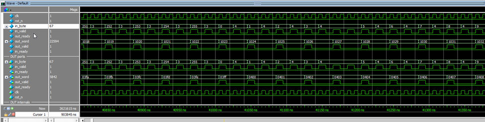
The simulation capture above shows the pipeline processing a stream of 16-bit words, each received as two bytes (LSB then MSB). Each word is reconstructed as soon as the second byte arrives, processed through the entire RNS chain, and then output after a fixed delay. For each injected word (e.g., the pair 254/3, i.e., 0x03FE), the output delivers the expected result (here 0x0400, i.e., 1022+2 modulo 16 bits). Input and output handshakes are tightly paced: the input is always ready, and the output publishes one result per pipeline “tick.”
In terms of latency, there are exactly eight clock cycles from receiving the MSB to the output result — corresponding to the pipeline depth (all internal stages propagate in 8 clock cycles). In practice, the module runs at the input stream’s cadence, with maximal throughput determined by byte feeding rate (here, one word every two cycles due to the 8-bit input bus).
Bottom line: it works. It does +2 — it’s admittedly heavy for just a +2, but it’s a full proof of concept. There’s no duplication or data loss. It counts to 65,000 in under 2ms, one word every 20ns… Real-world hardware testing will follow.
These results show that the entire pipeline, including the modular operations, binary→RNS conversion, and final RNS→binary conversion, is functioning correctly (no errors in the LUTs or the conversions).
Rest of the Design
The rest of the code closely resembles the 8-bit case. The structure is identical, but the precomputed tables are more numerous and larger, resulting in a total memory footprint of about 3.5 kB.
Outlook and Technical Comments
There are two major steps left before this project is “feature complete,” per the initial spec. This topic is, to me, genuinely interesting. It may enable truly low-cost, low-energy signal processing — but only for “fixed pipeline” architectures: comparisons and non-linear operations (especially divisions) are heavy in RNS, but for FIR, time-domain correlation, and similar tasks, RNS is a strong candidate when you need massive dynamic range.
Additionally, RNS offers a natural path to redundancy, thanks to its inherently parallel structure. In any context where error management is critical, this could open new opportunities.
But here, the objectives remain simple:
- Replace the “+2” with a functional FIR filter of 64 or 128 elements.
- Wire up the hardware to a real ESP32 and observe real-world behavior.
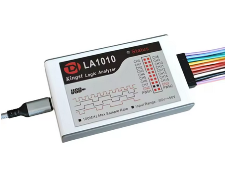
For hardware testing, I purchased this 16-input logic analyzer to observe the 16-bit output bus directly (50€ for 100 Mhz). The 8-bit input stream will be generated by the ESP32.
Discussions
Become a Hackaday.io Member
Create an account to leave a comment. Already have an account? Log In.