mircemk
Generally this type of instruments are divided into Contact-Based Meters wich Measure charge by direct contact with a surface and Non-Contact (Field Meters) that Use electrostatic induction to measure charge from a distance. Another division is based on the duration of the measurement, namely momentary checks in different locations and Continuous 24/7 Monitoring Systems.
In this project I’ll present a circuit design for a continuous static charge monitor that you can build or adapt. This design focuses on non-contact electrostatic field sensing, real-time voltage measurement, and output signaling.
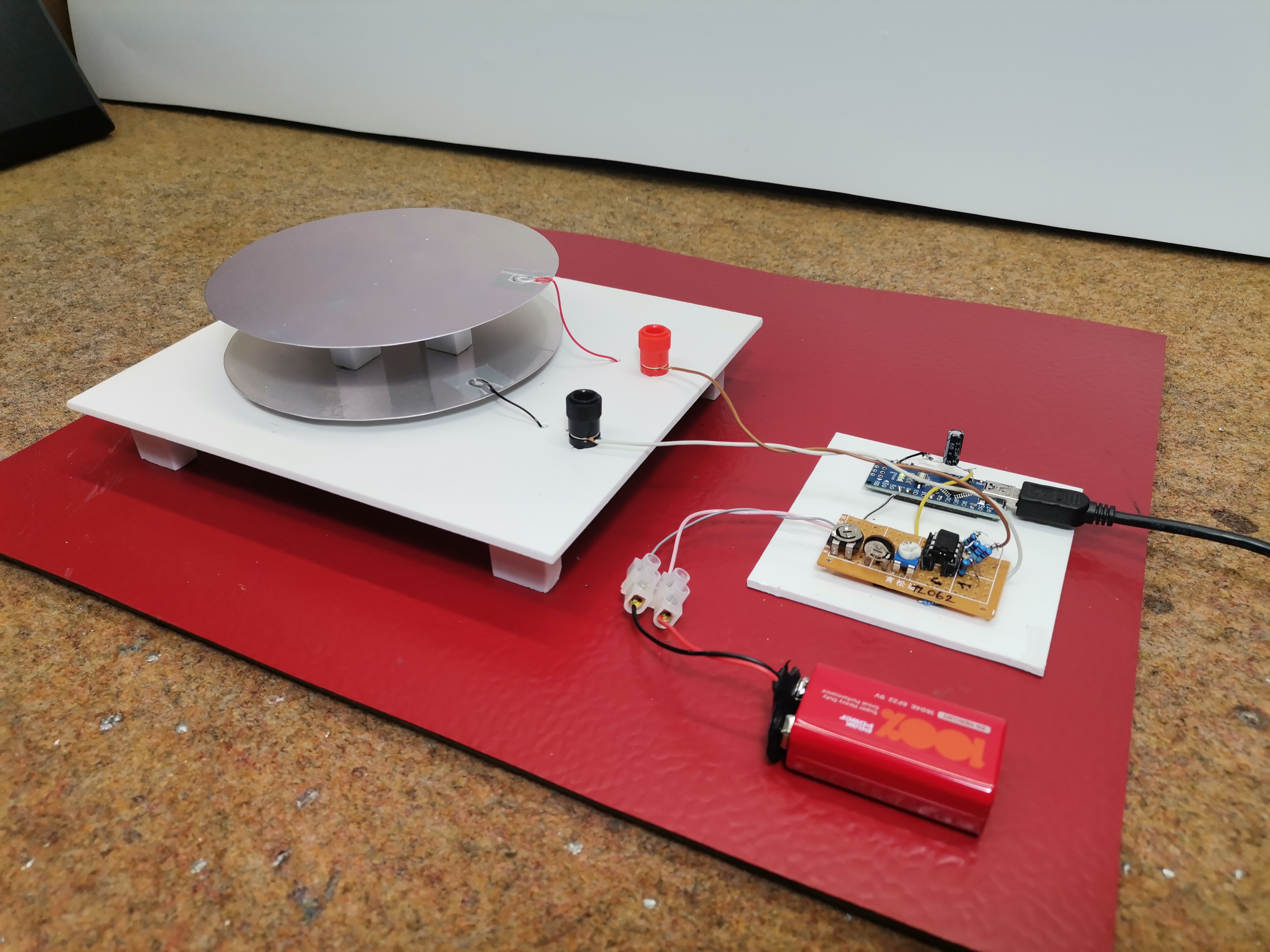
The device consists of three basic parts: a detector, an electronic part, and a unit for displaying and logging the result. Now I will explain each part individually.
This project is sponsored by PCBWay . PCBWay officially launches the first-ever 3D Printing Design Contest. All 3D printing enthusiasts can participate in both categories: design a 3D model based on PCBWay’s official mascot "Eon, " or create your very own original character. For the best projects are provided valuable prizes ranging from 200 to 500 dollars + certificates. PCBWay has all the services you need to create your project at the best price.

- First of all, about the detector, it can be said that this is the most important part, considering that it is used to detect and receive the static charge. It consists of two metal plates placed parallel at a certain distance and insulated from each other. The sensitivity of the detector is directly proportional to the surface area of the electrodes and inversely proportional to their distance. This means that the larger the surface area, and the smaller their distance from each other, the greater the sensitivity.
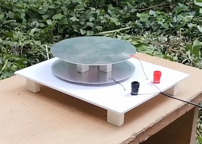
This time I will not go into further detailed analysis of the method of creating and manufacturing the sensor, I will just tell you that based on the many tests I have done previously, this is a certain compromise between the sensitivity and stability, accuracy and practicality of the sensor. Specifically, the surface area of each of the electrodes is about 115 cm2 (diameter is 6cm), and their distance from each other is 2.5 cm. Also, their shape is not chosen randomly and it has a circular shape, in order to reduce the so-called "leakage" effect. This is the simplest type of electrostatic charge detector and responds best to changes in electrostatic charge over time, which practically means that the charged object has to be moved close to the detector as we will see later in the demonstration. This is not practical in the case of measuring an Atmospheric Charge Monitor, where a Field Mill detector is used which uses rotating or vibrating conductive plates and generates an AC signal whose amplitude is proportional to the field strength.
- The next part of the device is a relatively simple electronic circuit consisting of an OPAMP JFET IC TL071 which functions as a comparator and amplifier of the signal generated by the detector.
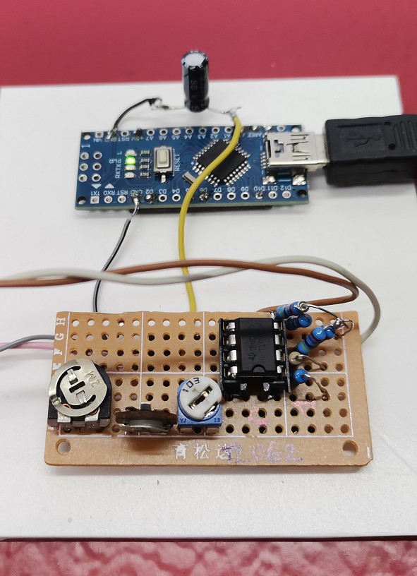
To briefly explain the adjustment method, we place the potentiometer P1 in the far left position (that is, a resistance close to the maximum), and P3 in the middle. We connect a voltmeter to the middle terminal of P3 and move the potentiometer P2 until the voltmeter reads 0 volts. At that moment, the detector is most sensitive and now with the potentiometer P3 we can adjust the range in which the voltage that we bring to the microcontroller will move. Now we bring the signal to the microcontroller, in this case Arduino nano which has the function of processing this signal and sending it to the PC software where we can visually monitor the values and changes. For this circuit you need to upload the given simple code in a way that has been explained many times before. For those DIYers who have no experience with microcontrollers, I can say that instead of a microcontroller, a digital...
Read more »