 Ruslan Nadyrshin
At first, my idea was to create a small standalone panel that could be easily carried in a backpack or pocket. The LED matrix determines the size of the device. Therefore, it was important to select compact LEDs that offer excellent brightness.
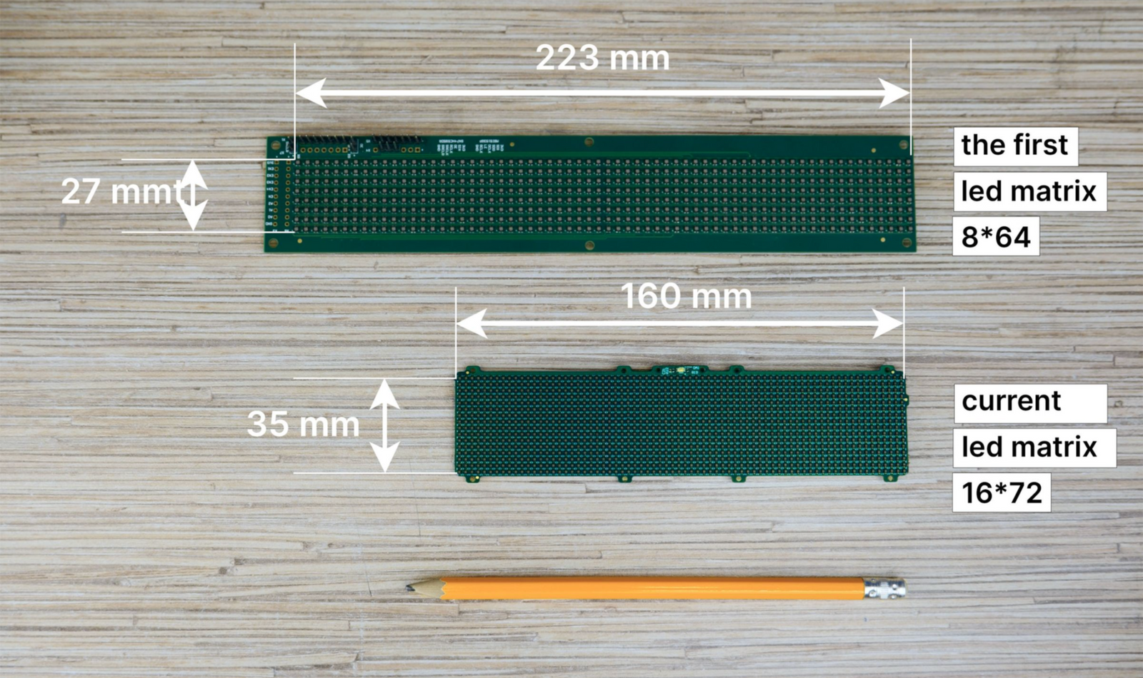
The original matrix was 64x8 pixels: 2.1 x 2.1 mm LEDs at 1.6 mm apart. However, that size made the device non-portable. Here’s a comparison picture with our current, smaller prototype.
During the selection process, we targeted LEDs smaller than 2 mm for a denser matrix and a more compact device. After considering options based on size, brightness, and cost, we prepared a comparison table for mass production.
| 1 | P4-1010RGBTA1-0.4T-A | 140 | 400 | 120 | ||
| 2 | MHPA1515RGBDT-S | 800 | 1100 | 130 | ||
| 3 | 18-038T/BDGAR6S1-S06/10T | 94 | 300 | 60 | ||
| 4 | NH-B1212RGBA-HF | 58 | 175 | 25 | ||
| 5 | NH-B1010RGBT-HF | 35 | 55 | 10 | ||
We used a specially designed board to assess the brightness and color rendering of the selected LEDs: 8x8 pixel matrices for the selected LEDs, covered by a 25% transparent tinted film. We displayed various characters to compare brightness and color. LED No.2 was the brightest, but at a kit cost of $50, the retail price for a single BUSY Bar would start at $400. It does not work for us. LED No.1 was also bright and compact, but similarly unaffordable.
Upon reviewing, we focused on options 4 and 5, differing in size and brightness. Eventually, option 4 was chosen, favoring size over brightness. After some bargaining with the manufacturer, we secured a $4 price for 1152 pieces. Having decided on LEDs, we can move forward to changing the design of BUSY Bar.
Stay tuned
If you enjoyed this project and its development story, follow for the latest updates and feel free to share your feedback.
Discussions
Become a Hackaday.io Member
Create an account to leave a comment. Already have an account? Log In.