One challenge I've run into is that the cable lengths is very large at "lower" frequencies. While I could try things out at GHz level frequencies where this is no longer an issue, it would be nice to experiment at 20MHz or lower to be able to use some parts I have laying around, along with basic test equipment, like a function generator and scope, and standard probes.
For example, let's assume a 10MHz source frequency. The period (T) for 10MHz is 100ns. The cable needs to be T/4, which works out to a cable delay of 25ns. The propagation velocity in a cable would be a bit under the speed of light (c) - let's say 0.7 * c = 2.1E8 m/s. The cable length needed would be about 2.1E8 m/s * 25E-9 s = 7m (23ft)! That's a pretty darn long cable!
What can we do about this? Well, old school CRT oscilloscopes offered some inspiration. They used a delay as an analog memory device to be able to view a bit of signal before the trigger point. Sometimes, they would use a long coil of regular coax. But some used a more elegant solution - a special transmission line with much more delay per unit length. There were different variations, with one conductor wound in a helix to create a longer path length.
The simplest type of delay I could think of is a center conductor, with magnet wire wound around it in a single layer. That's basically what the cable shown below is. I used a 3mm diameter, 1ft piece of teflon tubing to give it some rigidity. I wound magnet wire along its full length, and fished a piece of hookup wire through the center of the tube to serve as my center conductor.
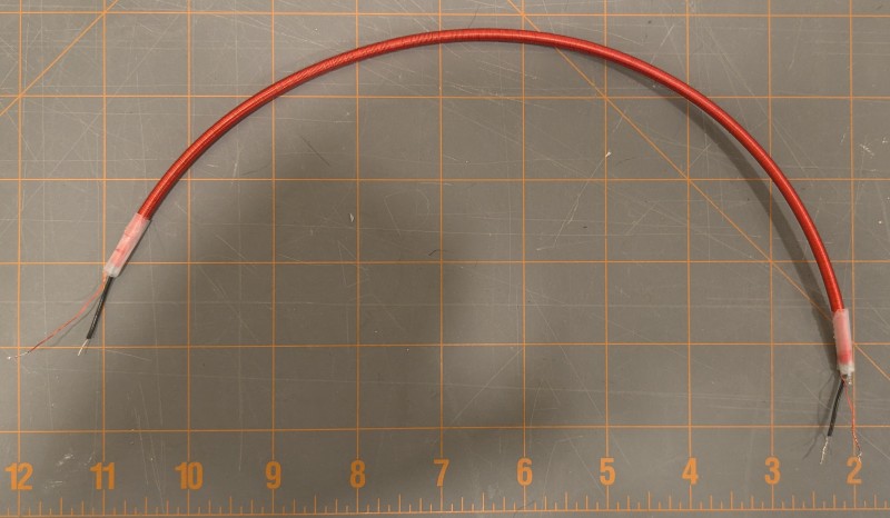 The cable's characteristic impedance worked out to about 1k ohms, which is actually a good value for generating high voltages at low power. I arrived at this value by measuring the cable's total capacitance with an LCR meter, then shorting one end and measuring the total inductance. They came out to 23pF and 23.8uH, then applied Zo= sqrt(LC).
The delay is easy enough to measure with a scope. I terminated the output with 1k, and used a 1k termination on the input, then applied a sine wave. With the termination resistances being pretty high, I had to be careful to avoid probe capacitive loading effects. Thus I measured at 1MHz where the probe's ~14pF capacitive impedance is more than ten times the termination resistance. I ensured the probe delays were well matched, and measured the delay with the scope. Channel 1 (yellow) is the input, and channel 2 (green) is the output, which is slightly delayed as expected. The delay measured about 20.3ns.
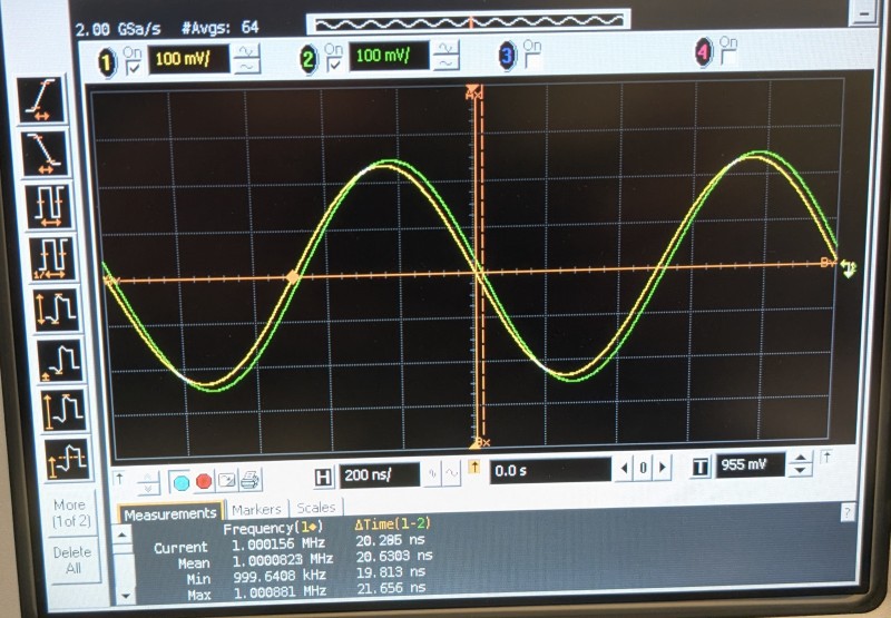 This is pretty good! A 1ft section of coax has a delay of about 1.3ns of delay, so this little section replaces 15ft of coax. The T/4 source frequency needed would be about 12.5MHz, which isn't too bad.
Discussions
Become a Hackaday.io Member
Create an account to leave a comment. Already have an account? Log In.