Close
0%
0%

overdriving LEDs, for the bees

overpowering daylight, to chase bees and hornets with a drone

Similar projects worth following
This project is about maxing out the LEDs. Can we drive them harder than the datasheet allows? We need this to overpower daylight, to see bees that wear retroreflective markers, as if was at night.

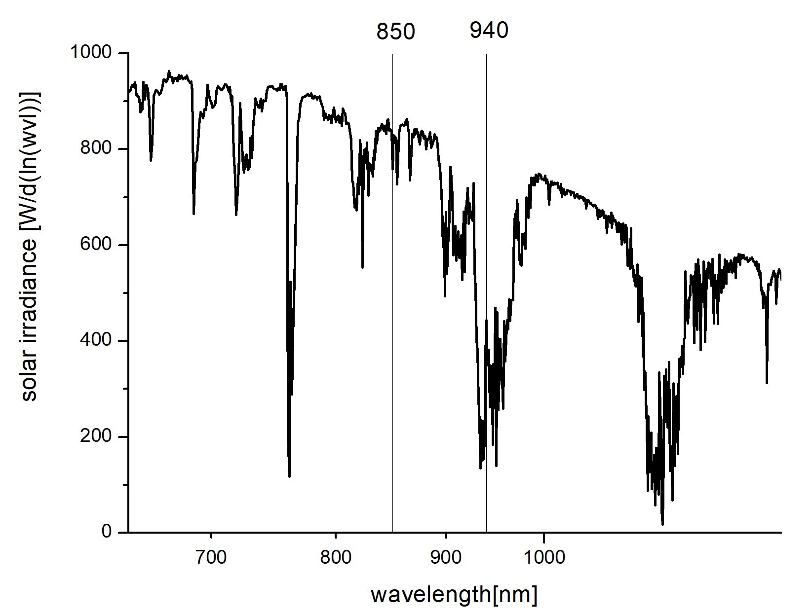
We glue a retroreflector to a bee (or a hornet). We illuminate it with an infrared LED projector. The reflector is then seen by a camera as a bright dot, which is detected by software and is used to track the bee. 

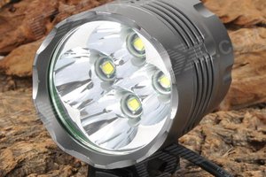
Because this is happening in bright daylight, we need a lot of light output to make the dot brighter than the environment. And because retroreflection is rather accurate (and also because it has to be carried by a drone), we are constrained in how many leds we can put on the projectors. So we really want to max out the LEDs.

For more details on our bee tracking efforts, see strawlab.org

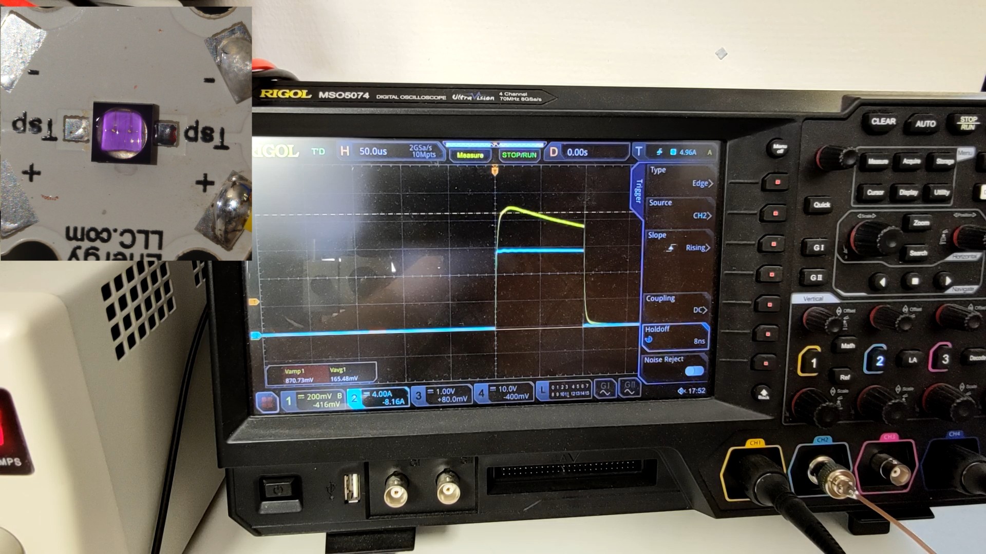
The led projectors are synchronized to camera exposure. The exposure time is 50 us at a framerate of 100 fps, so it's only 0.5% duty cycle. Because it's so low, cooling isn't really a problem.

This project is part of my job at Straw Lab, in University of Freiburg. It is funded by the VolkswagenFoundation Momentum Program (grant 98 692 to Andrew D. Straw), the Deutsche Forschungsgemeinschaft  (grant 543356743 to Andrew D. Straw), and the University of Freiburg.


Some aspects of this drone are open-source. https://github.com/strawlab/flo

see also our science paper on the tracking technology: Vo-Doan TT, Titov VV, Harrap MJM, Lochner S, Straw AD. High Resolution Outdoor Videography of Insects Using Fast Lock-On Tracking. Science Robotics 9(95), eadm7689 (2024) doi:10.1126/scirobotics.adm7689

  • aspects of driving leds at high currents

    DeepSOIC10/28/2025 at 14:00 0 comments

    we use an extremely simple drive circuit.

    It might look complicated, but the essence is dead simple.

    Each light has 21 LEDs connected in 3-parallel-7-series configuration. The driver for each light is just a 0.5-ohm resistor in series, a mosfet that turns on for the whole duration of the pulse, and an energy storage electrolytic capacitor to prevent voltage drop along the rather long and thin power supply wires. The constant voltage on that capacitor can be adjusted to adjust the pulse current; there is otherwise no active regulation of current going on.


    The voltage drop across the whole light at low currents (0.6A/led) is around 20V. The capacitor is at 40V, and at 18A, the voltage drop across the so-called "current limiting resistor" is 9V. So the light gets 31V, which is 4.42V / LED. It seems that at higher currents, LEDs become more resistor-like, and that this "current-limiting" resistor isn't doing very much. It seems that it can be removed altogether, though i'm a bit scared to do it.

  • the new VSMA1094400 (940 nm)

    DeepSOIC10/28/2025 at 13:39 0 comments

    We have recently decided to switch our bee tracking system from 850nm to 940nm. The main advantage of 940 nm is that there is about 3 times less daylight there, due to atmospheric absorption.

    I've chosen VSMA1094400 because it is rated to 5A pulse current, and it is also slightly smaller than the previously used SFH4715, so these can be packed tighter on a pcb.

    This time, i've recorded the overcurrent test on video.

    The results are, the LED has failed while i was raising the current from 10 A to 12 A. This time i was using 100us-long pulses (because that is set to be the safety limit in the driver board, so that the leds are not blown if the camera exposure is set too long by accident). This is more than twice as long as i was testing the old LEDs at. So i conclude that the new LEDs have basically the same peak current capability as the old ones, despite being rated to higher currents by the manufacturer. And i've decided to run the new lights at the same 5-6A to each LED.

    The lights did survive the day of test flights, and we were able to successfully chase an asian hornet with our drone (after a few failed attempts though). The lights remained on (pulsing 50 us / 10 ms, as they normally do) for the following night by accident. Nothing failed, except that the lights have unglued themselves (they seem to be running a bit hotter than the old 850nm ones).

    The oscilloscope trace has an interesting feature when the LED was about to fail.

    The blue trace is current, the yellow trace is light output.

    Note how the light output is decreasing significantly during the course of the pulse. I suppose it is the junction getting extremely hot, which reduces the quantum yield of emission. If that is the case, i can estimate the junction temperature from this drop. This drop is about to 84% of initial, so by the plot from the datasheet, the junction temperature at the end of the pulse is approximately 110 degC.

  • the good old 850 nm SFH4715AS

    DeepSOIC10/28/2025 at 13:19 0 comments

    SFH4715AS has been serving us well for about two years already.

    It has a rated peak current of 3 A, but we've been using it at 5-6 A with no problems.

    Back then, did a test on how much pulse current it can actually survive. I don't have much records on how it was done, apart from that the pulses were 45 us long, that the led failed at 12 A, and it has lasted for minutes before giving up.

    And a photo of the blown led:

View all 3 project logs

Enjoy this project?

Share

Discussions

Similar Projects

Does this project spark your interest?

Become a member to follow this project and never miss any updates