Dealing with temperature measurements might sound simple—after all, temperature is part of our everyday life. But obtaining precise measurements is a different story.
There are several pitfalls: component tolerances, ADC variations, changing battery voltage, environmental temperature shifts, and the imperfections of the sensor itself. Even the circuitry that connects to the sensor can introduce errors.
So how do we handle all of this?
The PT100 Sensor
The PT100 is made from a platinum alloy, providing a nearly linear resistance-to-temperature relationship across a wide range. These sensors typically operate from extremely cold to extremely hot temperatures—far beyond the range humans normally experience. Since I only need to measure between –20 °C and +40 °C, the sensor is sufficiently linear in this region. That means I can avoid complex conversion formulas and still achieve good accuracy.
But does this already introduce some inaccuracy?
The Circuit
I chose a Wheatstone bridge, as it is a highly accurate method for measuring small resistance changes. There are dedicated PT100 measurement ICs with SPI interfaces that can deliver temperature values directly, but I wanted to keep the design as cost-efficient as possible. I’m using such an IC in my mock-up as a reference for comparison.
For amplification, I selected the TLV9002S operational amplifier. Its low offset voltage can be handled in software, and it provides two channels plus individual shutdown pins—useful for reducing power consumption in a battery-powered design.
The PT100 is connected using a 3-wire configuration. This may be unnecessary with short cable lengths, but I want to evaluate the potential benefit.
Component Tolerances
All bridge resistors are 0.1%, which already helps improve accuracy.
ADC
Espressif microcontrollers are not known for their highest-quality internal ADCs. However, with proper calibration functions (beyond the standard analogRead() performance), results can be significantly improved.
Some deviation may remain—but we’ll see how well we can correct it with some additional calibration.
Varying Battery Voltage
Battery voltage fluctuations can distort resistance measurements. To mitigate this, I supply the measurement circuit from a regulated 1.8 V rail. The ADC then uses programmable gain to utilize the ADC range more effectively.
Even with early tests using 1% resistors, a basic op-amp, and simple code, the results are promising.
Calibration
For calibration three measurements are necessarry:
- A low temperature (like -10°C)
- A high temperature (like 30°C)
- At 0°C.
To emulate the temperature I make use of a known resistor. With the PT100 formula I can calculate the temperature at a given resistance.
The software calculate the linear graph y=mx+b or T=mU+b. Now every measured resistance can be converted to a temperature and all components that does not change (thus soldered) are part of the calibration.
The relative temperature (the chaning resistance) is now correct.
But one error remains: The absolute temperature. To calibrate to a known temperature there is only one method available without expensive equipment: Ice water. It should have 0°C. If the sensor is in this water the absolute temperature can be calibrated. More precise the sensor element with its tolerances is calibrated. The taken value from the ADC can be substracted from the final temperature calculation.
All together should give a precise measurement.
Here is the Wheatstone bridge I’m using:
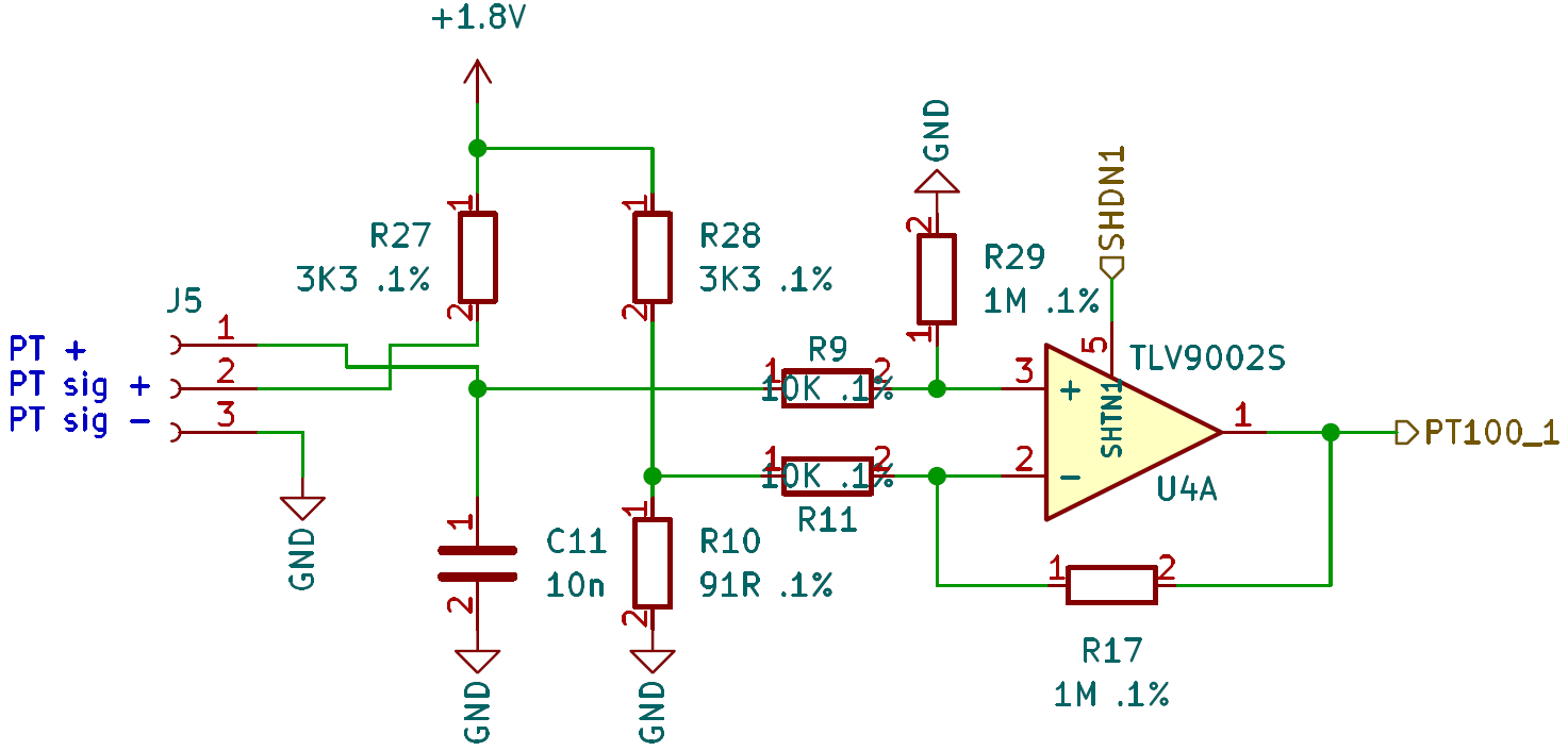
R10 sets the minimum temperature (91R ~-25°C). R27 and R28 are current limiting resistors and part of the bridge. R17 and R29 sets the amplification of the difference amplifier. 1.8V ~ 45°C.
Discussions
Become a Hackaday.io Member
Create an account to leave a comment. Already have an account? Log In.