Assembly
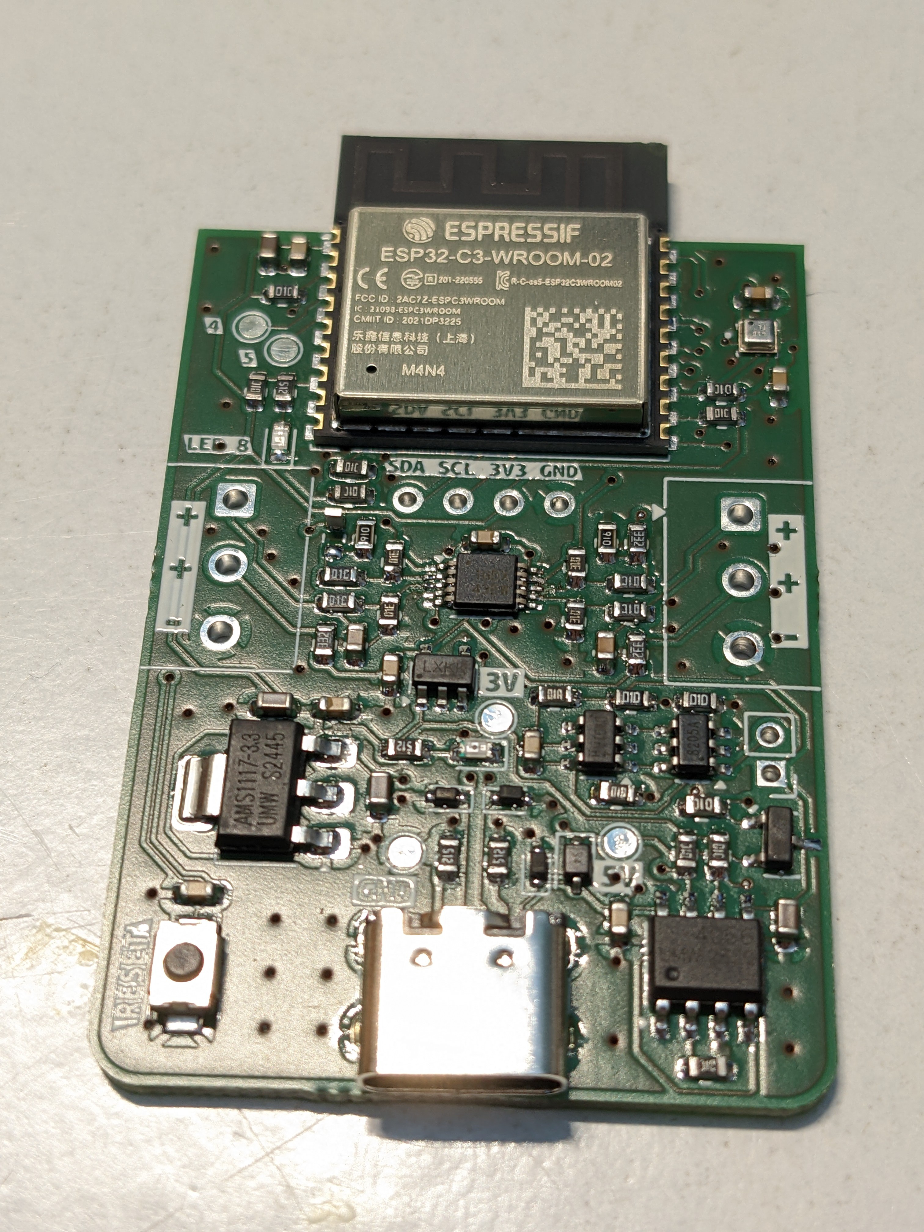
The PCB finally arrived, and I assembled the first board.
I was initially worried about the quality of the solder paste application through the stencil. First, there’s the USB-C connector, which absolutely must be soldered perfectly—there’s no way I could fix that with a soldering iron. The pitch is far too fine.
The second concern was the barometer chip: it’s tiny, and any rework would only be possible with hot air.
Surprisingly, applying the solder paste went quite well. Unfortunately, the pins of the barometer were completely shorted.
Nevertheless, I placed all components and “baked” the board on my cooktop. This is a proven method for me and works very well. 😄
After soldering, I checked most critical signals for shorts to GND or VDD.
Only two issues showed up:
-
The op-amp had shorted pins.
-
The barometer had SCL shorted to 3.3 V, meaning I²C would not work. The OLED wasn’t assembled at this stage.
Apart from that, everything else looked good!
Can you spot the tombstone?
First Power-On
Next, I supplied 5 V from my bench power supply with a 100 mA current limit. The board powered up, and 3.3 V was present.
Then I connected it to the PC to flash the firmware. As hoped, the controller was recognized immediately, and the Arduino IDE connected without issues. Flashing worked too.
Then the problems started.
Several things didn’t work—or appeared not to work. After many flashing attempts, I finally reverted to the very first firmware version. Somehow I had made the code worse over time.
With this restart of the firmware, the controller successfully starts an access point. The Wi-Fi credentials can be entered via the browser interface and are stored in flash. After a reset (which still doesn’t work correctly in software), the controller connects to the configured network.
Calibration with precision resistors also works. However, the op-amps do not output matching values for the same calibration resistor. After connecting real PT100 sensors, the first temperature readings were not too far off. I calibrated them in an ice bath, so in theory they should now always match.
But they don’t.
Maybe the sensors are too cheap—after all, I bought them on eBay…
Testing the Battery Charger
Using my power supply, I injected around 4 V to simulate a battery. Measuring at the 5 V test point, I got only 3.4 V—quite a drop. At the 3.3 V test point, only 2.4 V remained, and the controller wouldn’t even start.
I suspect the AMS1117 isn’t suitable for operation from battery voltage because its dropout voltage is simply too high.
Coming Up
Firmware improvements are ongoing. Some features—like MQTT—are still missing.
The hardware needs several corrections. I’m also considering adding a buck/boost regulator so the full battery voltage range can be used as the input.
Discussions
Become a Hackaday.io Member
Create an account to leave a comment. Already have an account? Log In.