 Gordon
Having several of these devices, I made a pogo pin adapter years ago to program via the ISCP pins accessable in the battery area.
My main reason for entirely replacing the back side of case was for three reasons
- Ability to modify device without cutting original case
- Possibly make device thinner
- Replace the 4 AAA with a single rechargeable LiPo
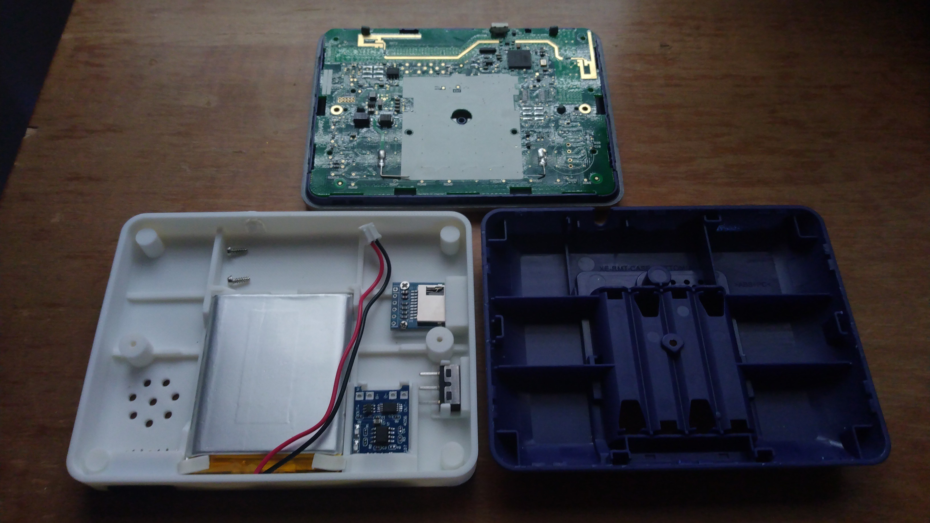
As you can see in the photo at the bottom, the original back Case has a space for the batteries, and other than that it is merely supporting the pcb.
Aside from adding the LiPo and charging module, I wanted to do some of the hardware hacks on device listed herehttps://github.com/fdufnews/SMART-Response-XE-schematics
Things I want to improve on this case design are as following, make it thinner, as of now it is only slightly thinner than original case. Using a thinner battery is the only way to accomplish this. As of now the battery I am using is using up the full space.
I also want to improve how the printed back Case attached to the front. The original case was held in place by snaps all around the perimeter, as well as one screw in battery compartment. This one screw was no longer an option as that is where the battery sits. So I opted to use the two PCB screws which originally only helped PCB to front.
Until next time.
Discussions
Become a Hackaday.io Member
Create an account to leave a comment. Already have an account? Log In.