Jeroen Brinkman
Twilight switch clock
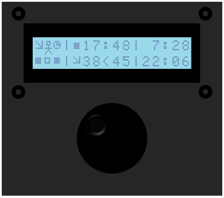
The clock uses a Real Time Clock (RTC), a light sensor, an Arduino Nano, a LCD display, a LDR for detecting the twilight, a PIR sensor to detect people and a solid state relay to make it work. Construction is very simple, because the twilight clock only uses standard, off the shelve, components. So no PCB manufacturing or perfboard soldering is required.
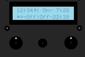
The clock has very sophisticated software, all parameters are software controlled
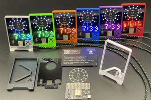
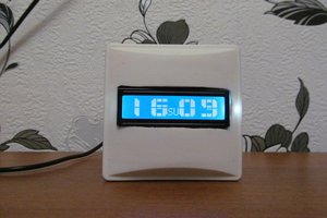
Casing
For durability reasons an aluminium case is used, however it could also be placed in an 3d printed case.
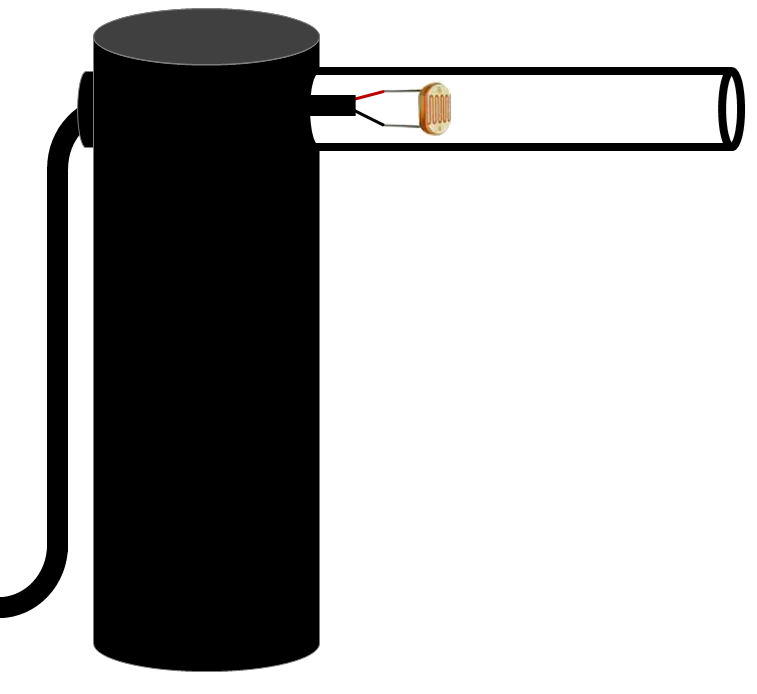
LDR Sensor
A small LDR sensor is used. Two aluminum pipes from 80mm are required. One with a 30mm outer diameter and one with a 10mm outer diameter. 3D printing would be an alternative. A 10mm hole is drilled in the top middle position of the 30mm tube. The 10mm tube is placed inside this hole.
The LDR is soldered on to a two-core wire. Be sure that both soldered wires are well insulated (use shrink wrap tube) and do not touch the aluminum tube. If more stability is required, some lead can be poured into the 30mm tube.
The sensor is placed in front of the window looking outward. The pipe ensures that it is not influenced by the inhouse lights.
PIR Sensor
The PIR sensor is placed in a drilled hole in the casing. I used a large rubber washer to heighten the sensor so that it fits in the casing. A proper placement of the sensor in the room is important to let it work properly.

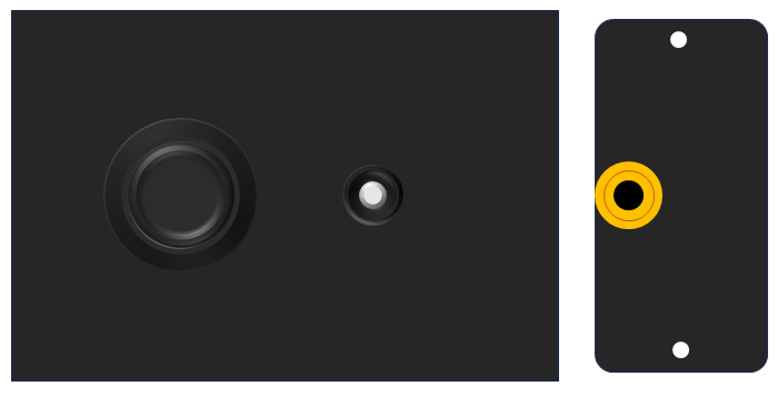
Remote control
The remote control, controls te manual override and circular switches the lights: ON - DELAYED OFF - OFF - AUTO. The dual color LED wil show the corresponding status: GREEN -BLINKING GREEN - RED -OFF. A standard male-male 3.5mm Jack extension cable is used, so that the proper length can be bought.
 Ratti3