 miana
mianaBasically, the idea here is to use FR4 PCBs as a structural component for a 3D lattice modular block and to connect them together with reflowed low-melt solder controlled by a MOSFET that just dumps a bunch of current through some chunky SMD resistors. This is intended to enable self-assembling modular robots. Here's a video for a conference paper on that for reference:
First, some background.
The goal of this work is to create a modular robot that can assemble modular structures/other modular robots. So, the idea is to have a geometrically compatible library of electronic blocks ("functional voxels") as well as purely mechanical ones ("mechanical voxels"). I won't really go into detail here, but you can check out the paper we wrote about this here.
Based on this overall goal, we can identify a few target specs to hit:
- Simultaneous mechanical + electrical connection for functional voxels
- Lightweight -- b/c robot needs to support its own weight in really unfavorable loading conditions, it's really important to keep this as lightweight as possible
- Cheap -- b/c we theoretically want a huge amount of these, and b/c most of the work I did on this project was while it wasn't attached to a specific grant, :p the mechanism needs to be cheap
- Reversible (we can undo it and redo it at least a handful of times without meaningful performance difference)
- Low effort to assemble lol
The system.
Based on these requirements, I looked through the literature on modular robots and identified the system used in Soldercubes as hitting most of these requirements, with the exception of low effort— they used a Field's alloy system that required a bunch of priming steps... I assumed low melt solder had advanced since then, and it has: Chipquik's line of Indium-based low temperature solders is easy to use and is offered at a range of temperatures that an SMD resistor should probably survive.
I also decided a directional joint, i.e. an actively heated board connects to a passively heated board and so on, would be lower effort to implement. This additionally forces a specific assembly sequence, which while it can have its drawbacks, practically tends make life easier. Because we're assuming an assembly direction from the get-go, this simplifies all of the connector layouts.
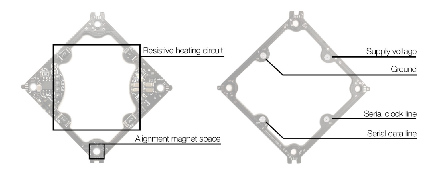
The overall system layout is: each robot/system has one primary microcontroller (ESP32-WROOM) that we can talk to over Wi-Fi from a central laptop that does all the path planning etc. This is networked to all the functional voxels/modules over an I2C bus. These periphery modules can provide a variety of functions, but in general they are all ATtiny412 based and contain one PWM enabled output and one analog input for free play, the I2C bus connections, and the resistive heating circuit. These receive regulated 5V power from an onboard linear voltage regulator, while the heating circuit (or any other output devices, e.g. hobby servos) receive the power rail voltage.
So, based on that, we transmit 4 lines between each voxel face: V_batt, ground, SDA, and SCL. For back-to-back connections, i.e. from block-to-block or between voxels, this is handled using the resistive heating circuit. For connections within a voxel or module, this is done using a soldered corner joint or using wiring.
Implementation.
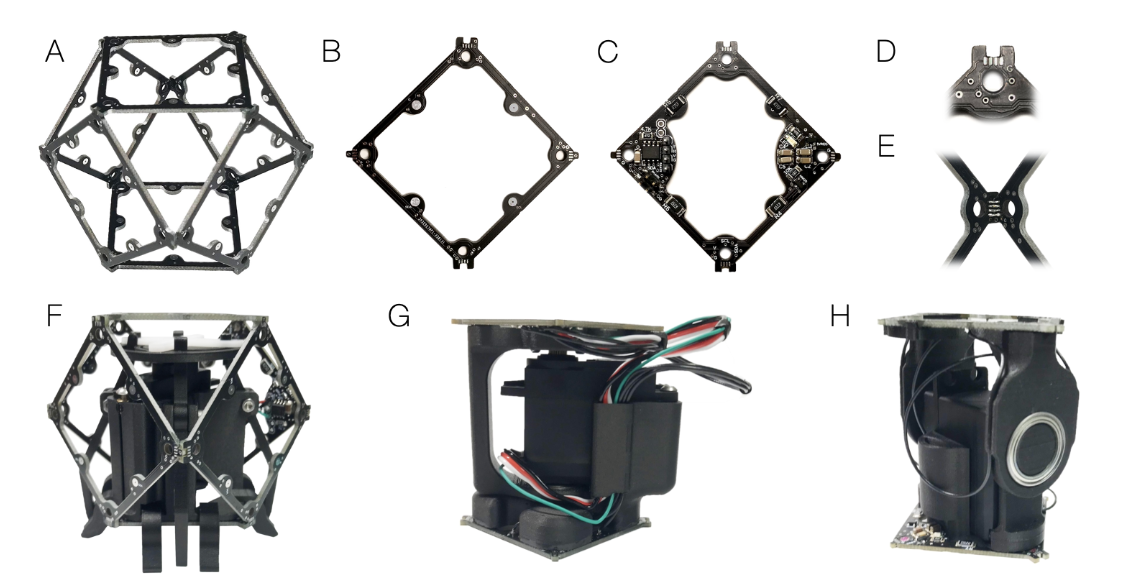
I used a 65 mm lattice pitch (the bounding box around the module is 65 mm side length). The PCBs are two layer boards from JLCPCB, with the routing as described above. B) Shows a passive face, where the four connection points are the spots on the middle of the beams. C) shows an active ATTiny412 based face, where the SMD resistors are visible. The empty holes at the corners are used for magnets, which help with fine alignment between the modules before the solder is reflowed. By adding actuation, we then get robot modules. F) is a gripper module for picking up/walking over existing blocks, while G) and H) are both joint modules. G is a wrist style joint and H) is an elbow style joint.
Details on the joint system.
In case it is useful, I want to note the parameters I've run with the joint system/robot system. I calibrate the system by running just the heating circuit using a DC power supply to identify what temperatures we hit at what power. The solder I prefer to use is In52/Sn48 ChipQuik blend, which melts at 118C. The resistors I used are 1W 0.25Ohm 2010 surface mount resistors (mostly these). The resistors are placed on the opposite side of the heated connection, and I drop a few vias per pad to help with both anchoring the pad and transmitting the heat. The resistors need to heat up enough to reflow the solder on the active board and the passive board well enough to form a good electrical and mechanical connection, so they tend to need to get a bit higher than 118C. In practice, I find good results when the steady state temp of the resistors is around 135-145C. In this layout, the resistors are in series, for a total resistance of 2Ohms (as we run the heating element, and as the modules get assembled, the overall resistance does change, which is almost problematic, but so far ok). At about 3.5V/1.75A/~6W with this circuit, we get to the temperature we want without cooking the resistors. Which is great! The resistors can handle >6x their rated power hahaha.
I then set the PWM for the circuit depending on what voltage the system is running at. It takes usually about 10 minutes total for the solder to reflow and sufficiently cool to continue assembly.
To form the connection, the heated side of the boards have the solder pre-applied, and the passive ones have flux pre-applied. I do this relatively evenly through chopping equivalent lengths of the wire-based solder and applying it to the pads. You may notice that we have four connections, but three point form a plane— is this a problem for making the connection between joints? Sort of— in practice, so long as everything eventually reflows and connects, it doesn't really matter what initially connects. However, if the ground pads are not connected, but the others are making contact, it tends to kill the I2C communications bus, which can be problematic as it prevents robot operation during the connection cycle (and sometimes requires the periphery modules to be power cycled). This can be avoided in a variety of ways. One option is to just stick more solder on the ground pad so it tends to be taller and forces a connection there. The other option, which is what I mostly did, which feels pretty inelegant and stupid, is just to stick a small piece of thin gauge wire onto the pad while applying the low melt solder. This forms a deformable and conductive element, not unlike the world's worst pogo pin. It works pretty well and is surprisingly reusable.
From there, for the robot to do the assembly, it only needs to place the modules so that the faces are contacting, and it doesn't need to be particularly accurate, b/c the magnets + eventually the surface tension will take care of that. The reflow circuit is then run (either as a manually sent command, or we can run the robot to try to detect if the next module is there or not, based on abusing the I2C bus just a lil). This then cooks the modules together, and on to the next module, and on and on.
Example Assemblies.
Using this version of the system, we made the assembler robots (and had an assembler robot make another), as well as a quadcopter, and a weird 8DoF quadruped. The quadruped ("ant") and assembler robots are all hobby servo based, and the quadcopter just re-uses that electronics set up to control some ESCs. Our paper on the assembly robots has some more details. Here's the assembly of the quadcopter and doing a tethered table top stabilization test:
We tried flying it once, indoors, powered via 20 ft cables, and this turned out to be a monumental act of hubris, as it promptly flew past the length of the cables and was smacked back down into the ground, at which point it spontaneously self-disassembled.
This is a locomotion test of the quadruped ant:
We made this as a hardware version of the RL ant benchmark and we were using it on a sim2real project that we have not completed... and possibly abandoned.... whoops. i thought it sounded funny with the music but now I vaguely regret it, sorry.
Problems.
The system overall works ok— well enough for the small demos I've shown, but not well enough for me to fully stick with it.
The first problem is largely an implementation issue— the connections pads are a bit small, so the joint strength was on the edge of what I needed. (Fine enough for normal operation, but the assembly robot has broken multiple times, and the quadcopter experienced massive spontaneous disassembly during its one test flight). This is arguably easy to solve— make the pads bigger, add more heating elements if needed. Toward fixing this problem, I arrived at another awkward-ness of this set up:
We're not using our power particularly efficiently. The resistors are pretty far from what they're heating, so I'm having to run them hotter than I'd like to make a good connection. To address both of these, I switched away from using the resistors and to using a 4-layer PCB stack up with one of the internal layers as just a resistive heating element: [to insert img/video].
The more fundamental issue with this setup is that it takes a relatively long time to do a connect/disconnect. This makes it pretty hard to do fast revisions/test different geometries. This also makes it harder to debug! Depending on what's going wrong, you often can't fully isolate or remove the problematic module, so that can force some more labor intensive debugs/fixes. There are some other additional challenges in terms of guaranteeing parallel-ness/alignment, but these are not so sever.
Basically, I'd say that this system works well enough for a set up where you don't want to do a lot of reassembly, and where you're pretty confident in your ability to place modules correctly the first time through.