Close
0%
0%

F.I.E.B (Friendly Interactive Exploring Bot)

A Can-sized robot powered by an ESP32, combining motion, sensors, and expressive displays to explore perception and personality.

adAd
Similar projects worth following
This project is a personal experiment in bringing motion, perception, and expression together inside a tiny desktop robot.

At its heart is an ESP32 microcontroller, chosen for its versatility and built-in Wi-Fi/Bluetooth connectivity. The robot moves using a two-wheel differential drive, balanced by a small rear caster. Power comes from a 3.7 V 2000 mAh Li-ion battery, charged and protected via a TP4056 module.

For awareness, four VL53L0X Time-of-Flight sensors form its main sensing array, providing distance data for navigation and obstacle avoidance. An accelerometer adds orientation and motion detection, allowing smoother reactions to movement and tilt.

Two 0.96″ OLED displays serve as the robot’s face and interface—one dedicated to system data, the other to expressive eyes that reflect its internal state or responses.
Every part of this build—from the 3D-printed chassis design to the wiring layout and control code

Component List

Core Electronics

  • ESP32-WROOM-32 Development Board – main controller, Wi-Fi/Bluetooth enabled

  • TP4056 USB-C Lithium Battery Charger Module – charging and protection for single-cell Li-ion battery

  • 3.7 V 2000 mAh Li-ion Battery – power source for the entire system

Motion System

  • 2× N20 500 RPM DC Gear Motors – differential drive movement

  • Dual-Channel PWM Motor Driver (L298N / MX1508 / similar) – speed and direction control

  • Ball Caster Wheel – rear stabilizer for balance and smooth turning

Sensing & Feedback

  • 4× VL53L0X Time-of-Flight Sensors – distance measurement and obstacle detection

  • 1× Accelerometer Module (e.g., MPU6050 or ADXL345) – tilt, orientation, and motion sensing

Display & Interface

  • 2× 0.96″ OLED Displays (128×64, I²C, 0x3C address) – one for data output, one for expressive eyes

  • I²C Bus Splitter / Multiplexer (optional) – for managing identical I²C devices

Power & Connectivity

  • On/Off Switch – inline power control between battery and load

  • JST Connectors / 2-pin Micro Connectors – quick battery and motor disconnection

  • Magnetic Pogo Pin Connector (planned) – for future charging dock interface

Structure & Mounting

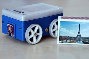
  • Custom 3D-Printed Chassis – designed in Fusion 360, houses electronics and sensors

  • Mounting Screws, Standoffs, and Spacers – for securing components

  • Motor Mount Brackets – holds N20 motors in alignment

  • Sensor Mounting Plates – adjustable front and side sensor positioning

Wiring & Miscellaneous

  • Dupont Jumper Wires (Male–Female / Female–Female) – prototyping connections

  • Breadboard / Perfboard – for initial wiring layout tests

  • Heat-Shrink Tubing & Cable Wraps – for clean wiring and insulation

Optional / Future Additions

  • Battery Voltage Sensor Module – to monitor remaining power on OLED display

  • Buzzer / Speaker Module – for audio feedback or status tones

  • IR Receiver / Remote Module – for manual testing and control

  • Wi-Fi Dashboard (ESP32 Web Interface) – for live telemetry and debugging

  • Auto Docking Charger Pads – for autonomous recharge testing

  • Planning

    Ad11/05/2025 at 14:00 0 comments

    The Journey So Far

    This desktop robot began as an idea to combine sensors, movement, and personality into a palm-sized machine — one that could navigate its environment and display emotions through simple expressive cues.

    Core Platform: ESP32 Brain

    The robot’s main controller is an ESP32-WROOM-32, chosen for its dual-core performance, built-in Wi-Fi and Bluetooth, and flexible I/O support. Its processing power allows simultaneous control of motors, sensors, and display outputs — all while maintaining network connectivity for future OTA updates and data logging.

    The ESP32 handles:

    PWM motor control for precise movement

    I²C communication with all sensors and OLED displays

    Battery monitoring and power management

    Serial debugging and configuration

    Drive System: Two Wheels + Caster

    Mobility is achieved through a two-wheel differential drive system powered by N20 500RPM micro gear motors, providing a balance between torque and speed.
    Steering is accomplished by varying the speed of each motor — no servo steering is required.

    To stabilize the chassis, a single rear caster (ball-style) supports the frame, keeping the bot balanced while allowing smooth pivot turns.

    Power System

    The bot runs on a 3.7 V 2000 mAh Li-ion battery, offering solid runtime for its small form factor.
    A TP4056 USB-C charging and protection module manages charging and discharge safety. The power rail splits to feed:

    ESP32 logic (3.3 V regulated)

    Motor driver board (5 V or VIN depending on configuration)

    Sensor and display I²C bus (3.3 V)

    The goal is to later integrate automatic charging via magnetic pogo pins or a simple docking plate.

    Motor Driver

    A compact dual-channel PWM motor driver connects to the ESP32. Each motor is controlled via one PWM and one direction pin. This allows proportional speed control and smooth turning maneuvers.

    Sensors: Environmental Awareness

    The robot’s “eyes” are four VL53L0X Time-of-Flight sensors, placed strategically around the chassis:

    Front-left and front-right for collision avoidance

    Left and right sides for wall following and spatial mapping

    Rear or angled sensor (optional) for backing awareness

    Each sensor uses unique I²C addresses, set dynamically at startup to share the same bus.
    An accelerometer (connected via I²C) provides tilt detection and motion feedback — letting the bot understand its orientation or detect if it’s been lifted or knocked.

    Displays: Expression and Feedback

    Two 0.96″ OLED displays (128×64, I²C) are mounted at the front.

    Display 1: System data (battery level, IP, sensor readings, etc.)

    Display 2: Animated “eyes” — giving the bot a bit of personality

    Both displays share the same bus (address 0x3C), but a multiplexer or secondary I²C address can be used to differentiate them.

    Layout and Wiring

    Everything fits around a custom 3D-printed chassis, designed to roughly match the footprint of an Arduino Uno — compact but with layered sections for electronics and sensors.
    The current wiring includes:

    ESP32 GPIOs for both motor channels

    Shared I²C for OLEDs, ToF sensors, and accelerometer

    Power distribution from the TP4056 board

    Motor driver VIN from battery rail

    Battery sense pin for voltage monitoring

    Software and Control Logic

    Initial sketches handle:

    Basic motor testing (PWM forward/reverse)

    I²C detection of sensors and displays

    Data visualization on OLED

    Serial feedback for debugging

    The next software milestones include:

    Sensor fusion for obstacle detection

    Motion logic with avoidance behavior

    Display animations for idle/active states

    OTA update integration

    Wi-Fi dashboard for sensor readouts

    Chassis Design

    The chassis design is being modeled in Fusion 360, with considerations for:

    Two motor mounts with alignment brackets

    Rear caster housing

    Front plate for ToF sensors and OLEDs

    Detachable top shell for battery and board access

    Clean...

    Read more »

View project log

Enjoy this project?

Share

Discussions

Similar Projects

Does this project spark your interest?

Become a member to follow this project and never miss any updates