 Michael Gardi
When I started my Type 30 reproduction project(s) I sent a request to the Computer History Museum (CHM) through their contact page asking if it would be possible to get some measurements of the Type 30 display. In mid-October 2025 I received a reply from an wonderful archivist at the CHM who kindly agreed to take some measurements for me.
A quick anecdote. While the archivist was at the CHM to get the measurements they were introduced to Peter Samson of Tech Model Railway Club and PDP-6 fame who was volunteering that day and let them into the PDP-1 room. ;-)
So I sent this photo:
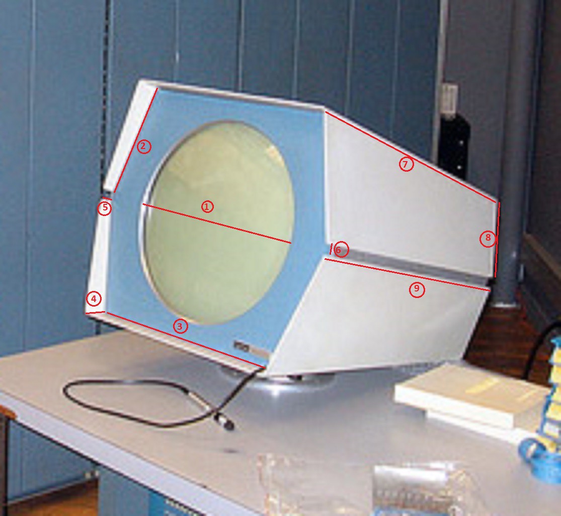
And received the following measurements:
- 14”
- 8 ½”
- 17”
- 1 5/8”
- 3/4”
- Same as 5 (above)—3/4”
- 26 1/4“
- 6 3/8“
- 25"
- The black cable of the light pen (not including rubber attachment nor silver pen) 17”
- The rubber attachment between cable and silver light pen 1 5/8”
- The silver light pen 6 ½ “
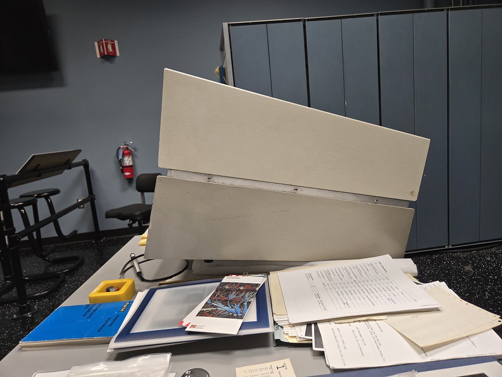
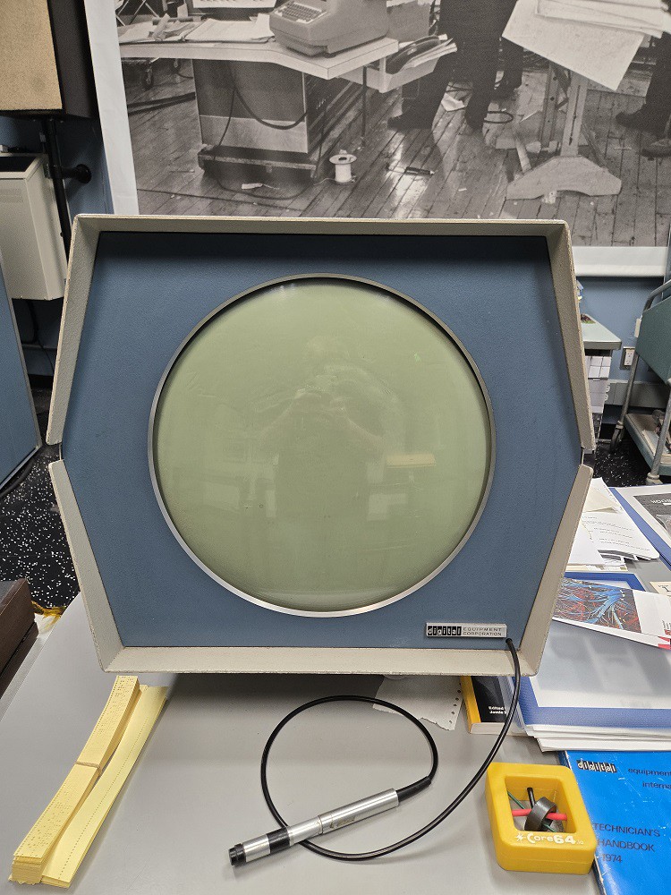
In addition they also sent me the following photos:
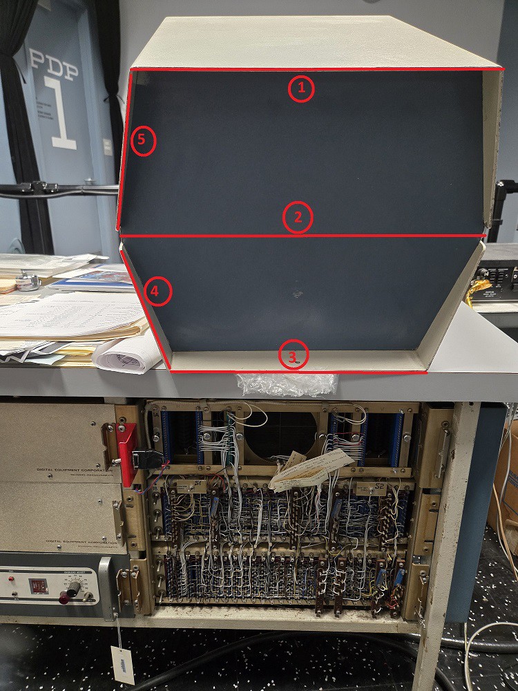
And measurements for the back (I added the red line and numbers):
- 12 3/4”
- 16 1/4 ”
- 12 3/4”
- 6 1/4”
- 6 3/8"
So a few things. I think these are some pretty cool pictures from the PDP-1 room at CHM taken in October 2025 not 60 years ago. The picture of the back (I had not actually seen a photo of the back till now) has a good view of the circuitry that presumably drove the display. I have to complement the restoration team. The monitor is at least 60 years old and looks great, and of course it works!
Looking at the measurements, the one number that surprised me was the 14" measurement of the round opening in front of the tube. I had read the following in the CRT 30 manual:
The DEC Precision CRT Display Type 30 is a 16-inch random-position, point-plotting cathode ray tube which permits rapid conversion of digital computer data into graphics and tabular form.
I made the assumption that the opening was 16 inches whereas in hindsight I'm sure now it was the tube face itself that was 16 inches in diameter. This is something I would never have known without the CHM's help. I had also read somewhere that the CRT was "19 inches" which I thought at the time was the diameter of the display but which I now believe is the length of the tube (especially given that the sides are about 27 inches deep).
With a 14 inch opening it means that the scale of my smaller reproduction with it's 8 inch opening is 8/14 or 57% scale which is only 1% larger than the 56% scale that the PiDP-1 console is. The large reproduction is actually 75% scale (10.5/14). No wonder it was so big.
Now that I have a more complete picture of the Type 30 display I would like to model the whole thing not just the front. While the front face by itself is fairly recognizable, I feel it is the shape of the whole monitor that is truly iconic.
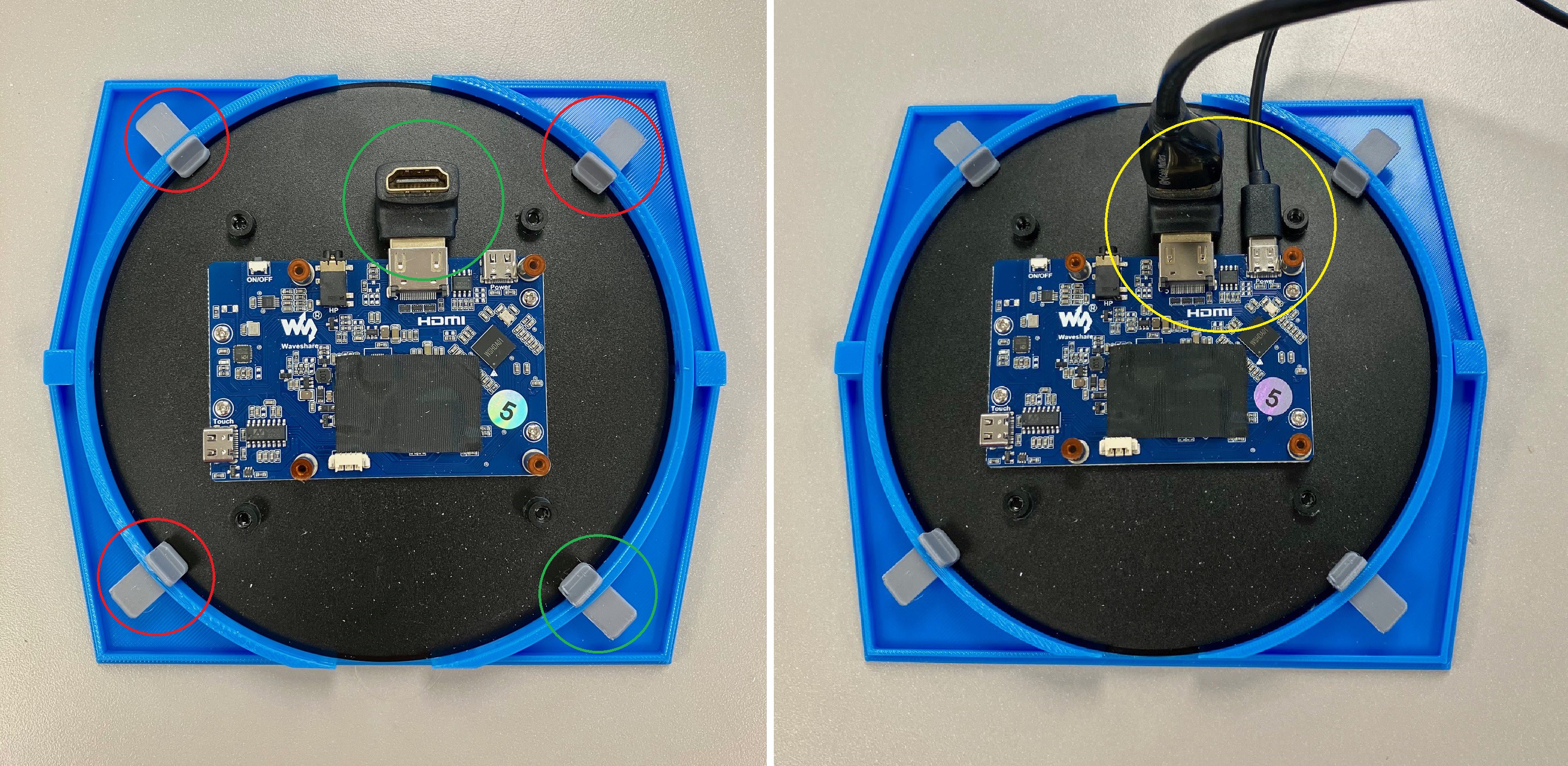
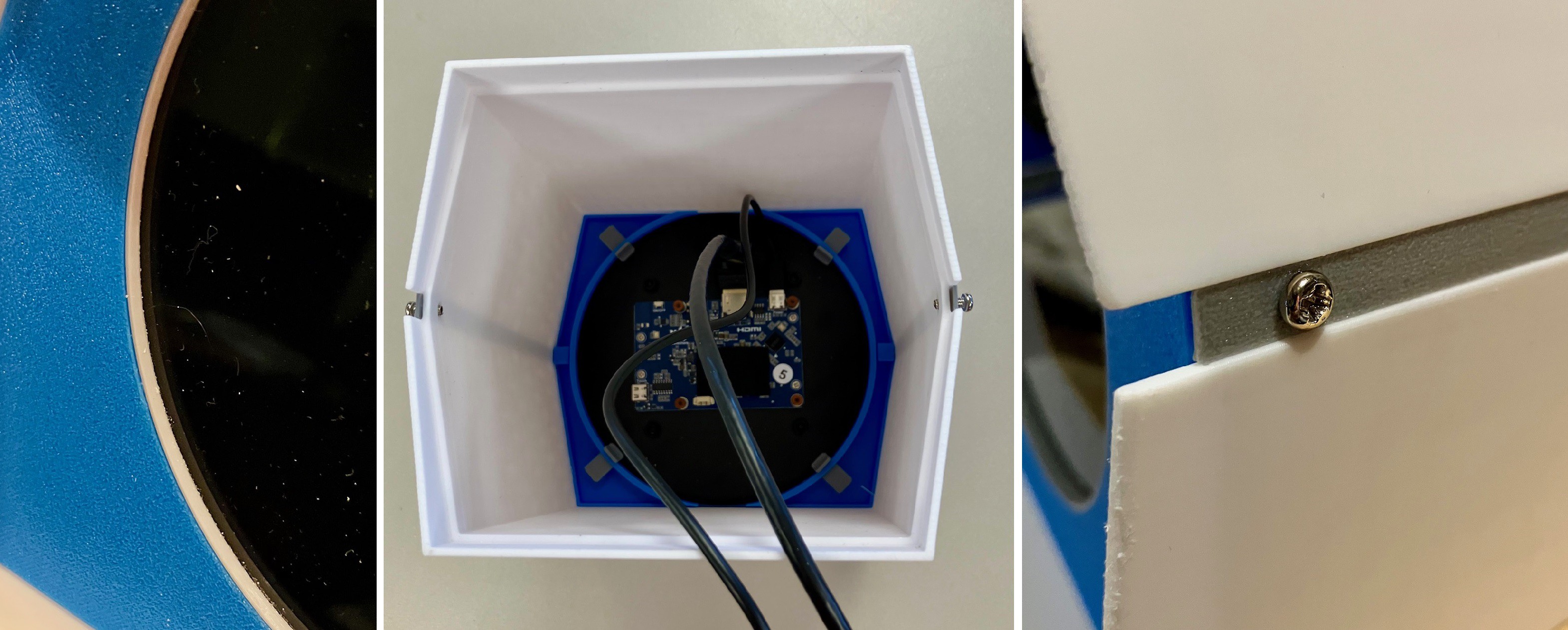
To keep the actual size down to something reasonable I first thought 25% scale might be good. That would mean that the screen opening would be 14 x .25 or 3.5 inches and there is a nice display that would work, the Waveshare 3.4 inch DSI LCD Compatible Display (https://a.co/d/aHfCzc6). But a couple of members of the Google Groups PiPD-1 Forum convinced me that targeting the Waveshare 5 inch display would be a better choice for a few reasons:
- The 5 inch display has an HDMI display (the 3.4 inch is DSI).
- Some members of the PiDP-1 Group have used the 5 inch display and like it for its sharpness, but also say you would not want to go much smaller for usability reasons (which usually means playing Spacewar ;-).
- The 25% scale might look a little "toy like".
So a 5 inch display it is. To have a 5 inch display means scaling the Type 30 at 36%! Third Time's A Charm.


 icstation
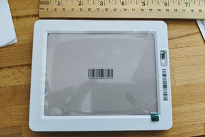
 Mike Szczys
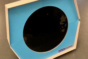
 Michael Hawkins
@michael: If you'd like the DEC logo on laser-engraved thin metal instead of card stock, I'd make one for you.