 Alex Xia
We're in pre-launch on CrowdSupply. Sign up to get updates!

Open-source Firmware & Schematics on Github.
The Inspiration
I'm a college student in EE--not the best, not the worst, which meant for me at lot of breadboard plugging at coffee shops and in libraries trying to meet deadlines. As it turns out, combined with Montreal's standard Canadian weather, filled with rainfall and snow, carrying a power supply is not really convenient. I got by for a while with a cut USB cable, stealing power from my laptop. Otherwise, I had a LiPO battery, which got me weird looks...
I got a few of those cheap-o breadboard supplies, and unfortunately they all either A) ran on inefficient linear regulators, or B) were quite large, unpleasant, and incompatible with USB-C stuff I already had. Though I ended up hacking a random PD trigger board for a while, the jumble of cables wasn't really ideal to carry around all day.
In an analog project where I had plugged some opamps, I started measuring some power supply ripple from the PD trigger board that was being amplified. Last straw for me.
The Design, and Engineering Constaints
I set out to design my own. Besides intuitive controls, I just love those projects that include a nice aesthetic display, and I wanted ProtoV to have one of its own, too. I set out to build with a few of my own design constraints in extra:
- Size: Handheld, and the user interface directly inbuilt.
- Connectivity: USB Type-C for power and data, with a possibility for programmatic control, and data logging from a computer.
- Adjustability: Dynamic range for voltage setting, and current limiting options.
- Form Factor: Built for breadboards, but has the options for other connectors via expansion cards.
- Electrical Capabilities: Low noise, high filtering capabilities, and high current handling.
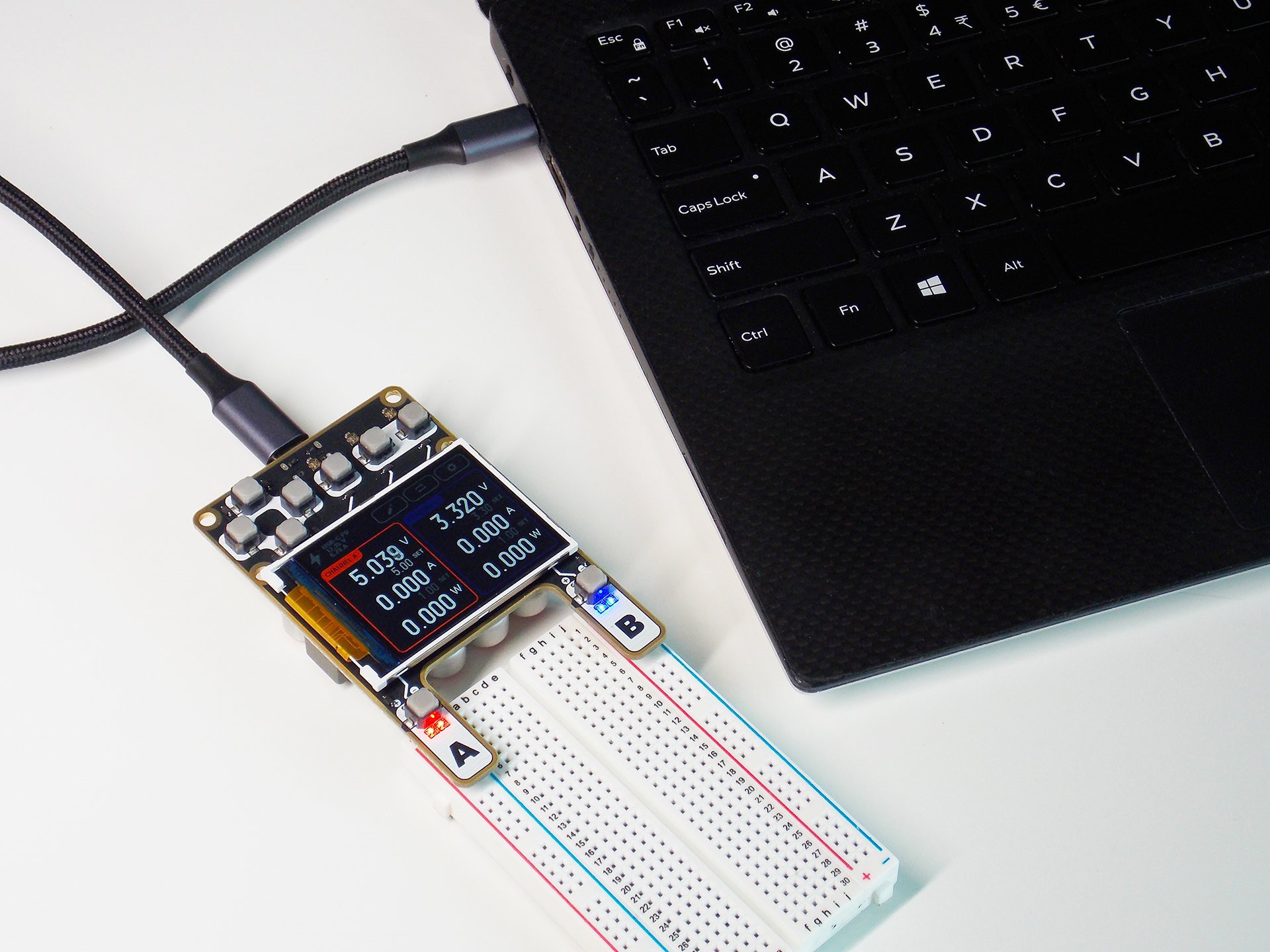
ProtoV MINI connected to a host computer, delivering both 3.3V and 5V rails into a breadboard.
The Power System
I wanted the maximum adjustability, and also current limiting. At the same time, it had to be efficient due to it being a portable device. That ruled out linear regulators. The variable input voltages due to the USB-C PD standard also made it impossible to only use buck or boost converters alone.
While browsing through options for buck-boost converter chips, I found this line from Texas Instruments, where the reference voltage for the boost converter could be adjusted internally via an I2C interface. It's destined to be implemented in modern USB Power Delivery (PD) compliant chargers--my guess, aimed at different manufacturers looking at an easy way to implement this technology. From my perspective, the output regulation of these chips were perfect for a portable supply, with diverse voltage and current adjustments, along with a small general footprint.
I quickly drew up a schematic for the LM51772, a four-switch buck-boost converter with all the above mentioned features, fitted with an INA226 power measurement chip at its output. That was the first test output test PCB for ProtoV.
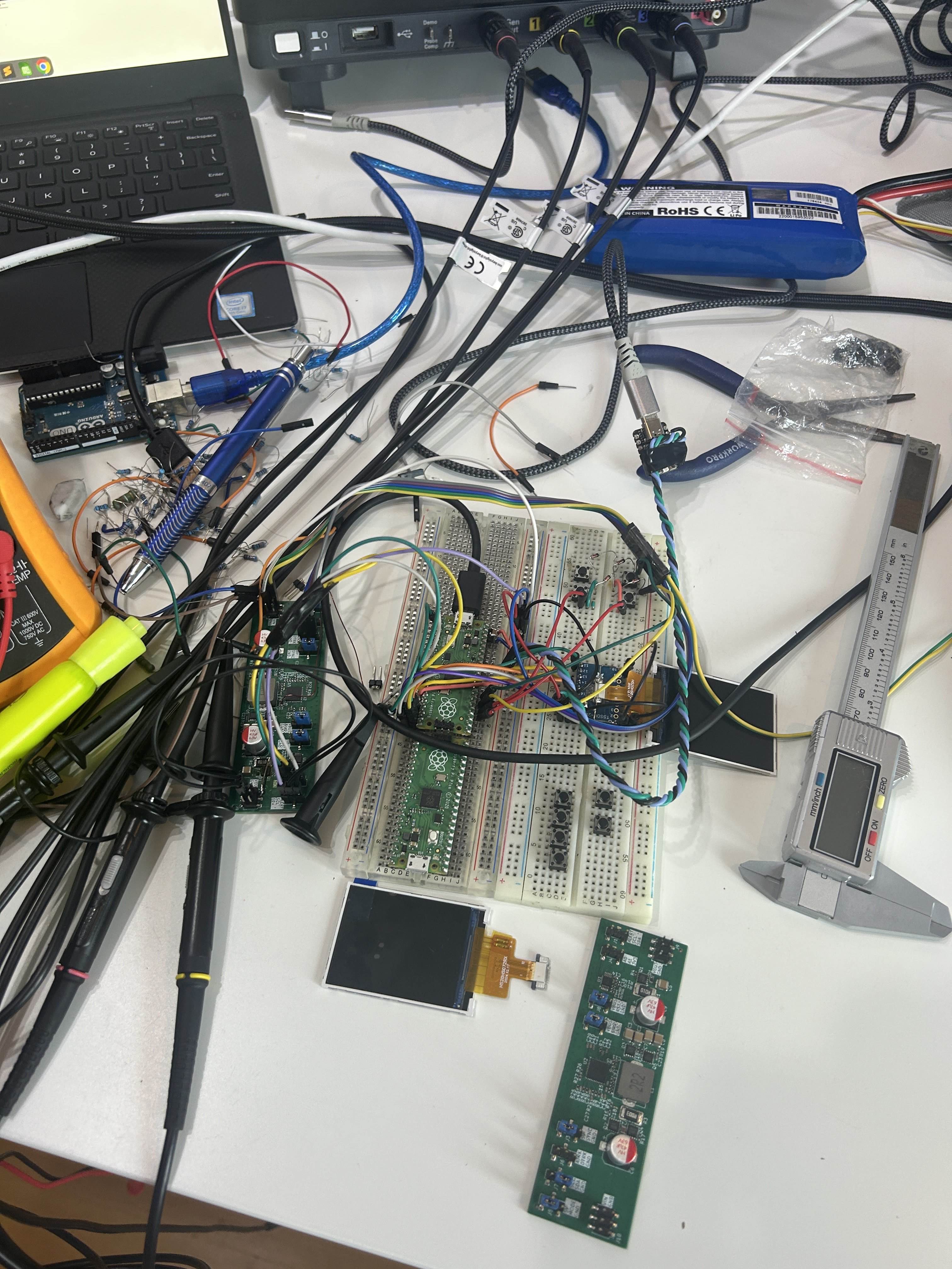
First hardware tests for buck-boost converter chips. The rectangular board features the LM51772 from TI. I didn't have a power supply at the time, so a poor blue LiPO battery was used to supply power during all those tests.
Voltage adjustment from 0-20V, 10mV steps. Current limiting from 0-5A, 50mA steps... All the features worked amazing! However, having to put four external MOSFETs due to it being a four-switcher was inconvenient in terms of footprint. I switched to the TPS55289, which, in turn, had the switches included within the chip. Two of those on each ProtoV unit makes up both adjustable channels.
The User Interface
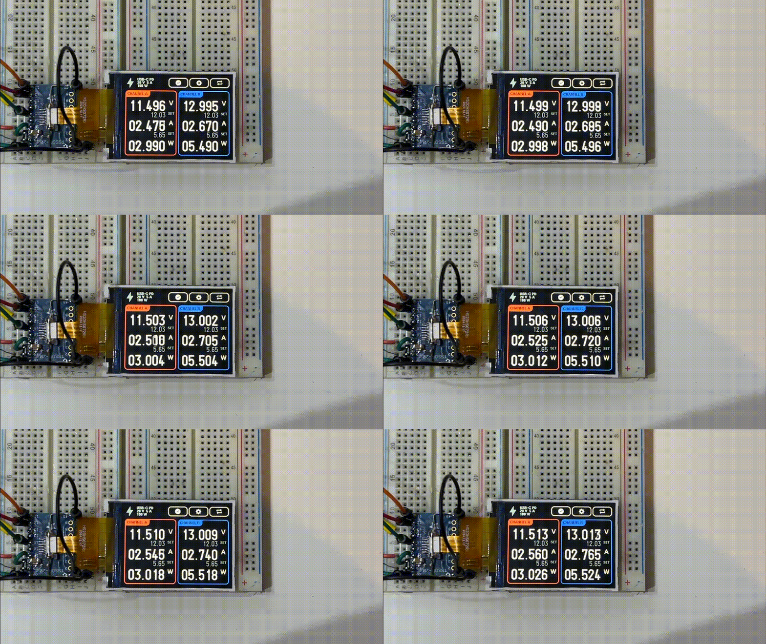
First UI demo running on the Embassy embedded framework, written in Rust!
Side thing: I love programming. Rust had popped up on my radar a while back, and I've been searching for an excuse to use it since. I found out the Embassy embedded framework, which I thought was perfect for this use case. I made a quick sketchboard of the UI, and drafted it up quick, so that it would show on the 2inch screen I decided on using.
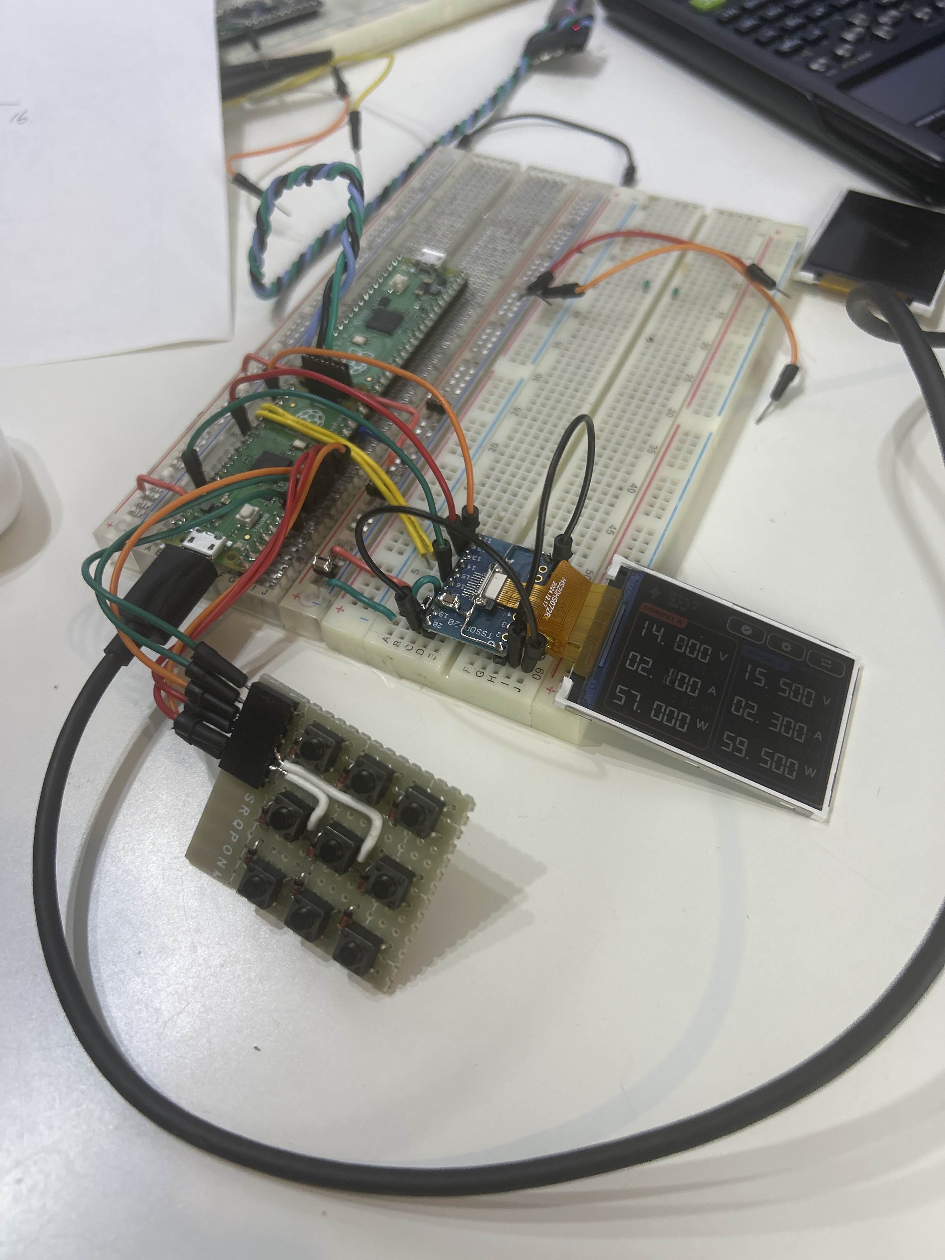
First UI unit testing setup, with a hand-wired button matrix.
To test things out further, small perfboard versions of the buttons I had made, just to test the software end of things while the first set of prototypes would get shipped out. A "bit more" Rust development turned into a lot of it...
The Full System
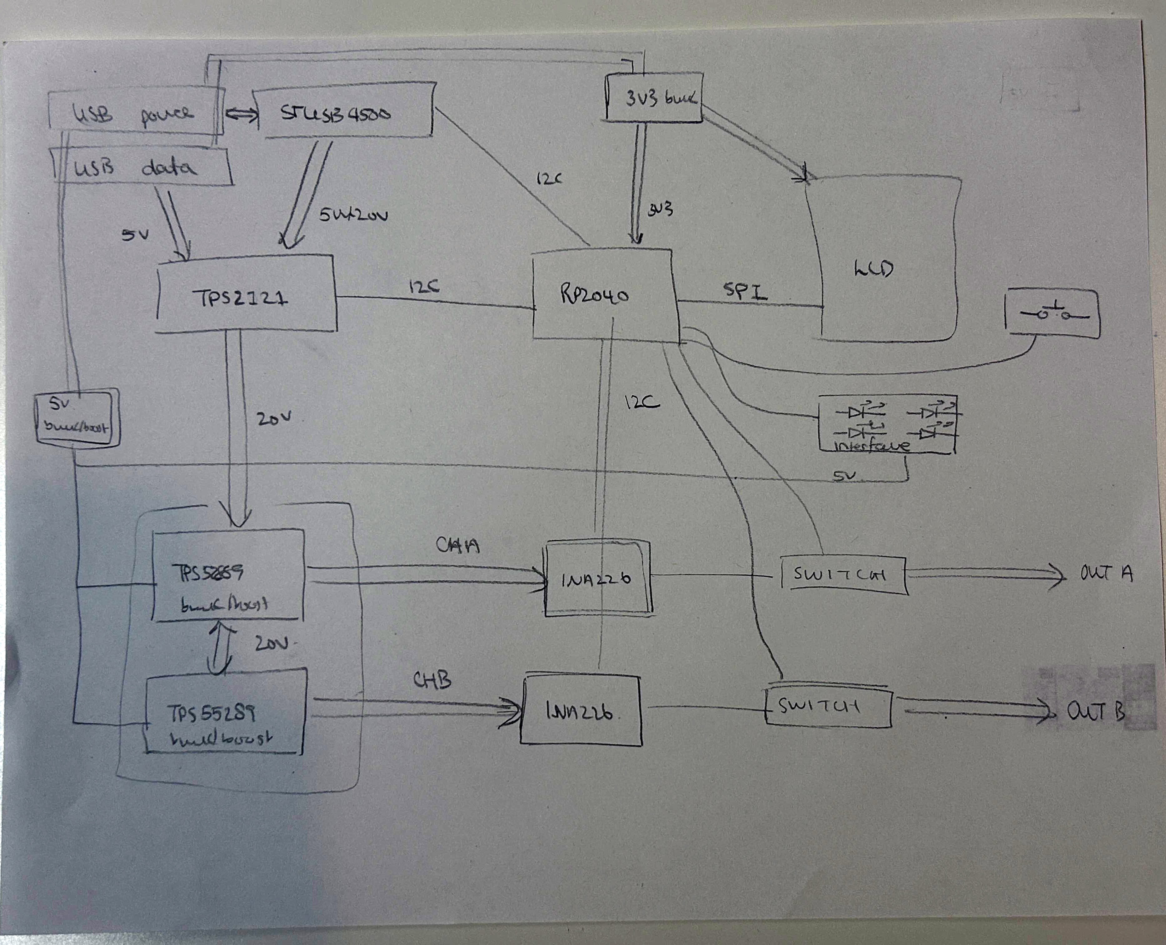
Prototyping block-diagram of the ProtoV power supply.
Combining everything together, I had a clear idea of what I needed to concretize into a final PCB board. A USB Type-C Power delivery (PD) input negotiates up to 100W, for the whole power supply to use. Mediated by the user interface and the MCU, an RP2040, the two channels' voltage and current limits would be adjusted, delivered, and finally measured.
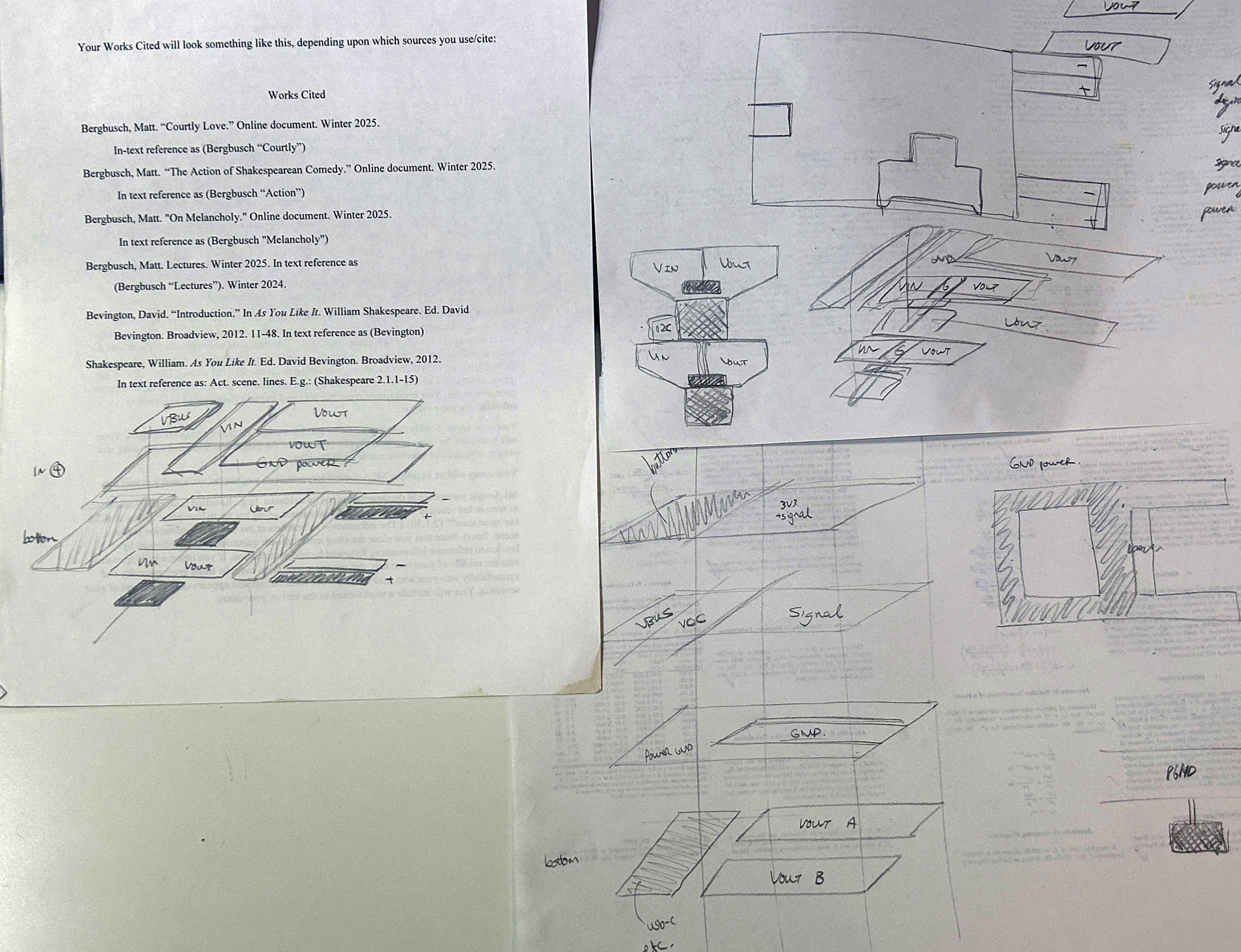
PCB power traces routing concept plans.
One of those "form over function" design choices I decided upon was to have the whole power supply fit within the footprint of a standard credit-card (85.6 mm by 53.98 mm). Though one could also argue it's "function over form," since that makes the device small... Anyways, power traces need to be hefty, and ground planes large so that the TWO switching converters in that tiny footprint won't act up. I settled on a six-layer PCB, with two inner layers as ground, and power traces doubled with via-stiching.
The First Units
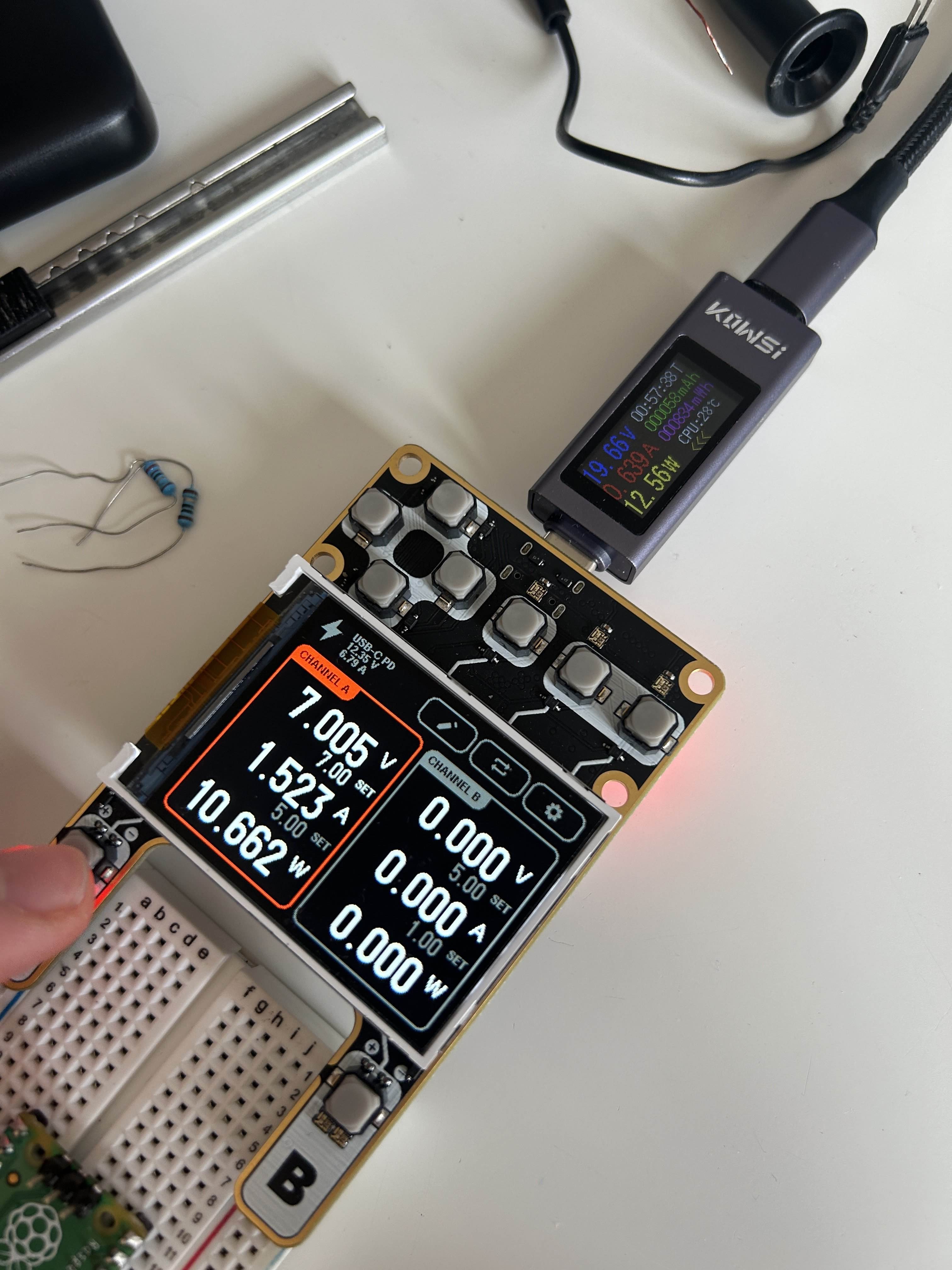
First manually assembled ProtoV unit, with the display mounted on top. Carrying out an efficiency test, measuring input power versus actually delivered power to the load.
Lo and behold, the delivery driver showed up with the first set of six-layer boards, with ENIG edges. I had designed the prongs with pin headers to stick out, so they would interface directly with the power rails of a breadboard. There's also some silkscreen markings to make the UI more intuitive: to properly delimit the D-pad controls, the various settings buttons, and channel enables. I flashed on the firmware I had been writing at the same time, and things worked out well, after a few hours of debugging here and there!
The Timeline
April 2025
- First prototypes and electrical tests.
June 2025
- Software development
- Arrival of the first batch of PCB units.
September 2025
- CrowdSupply campaign launches, sign up for updates!
- Electrical tests for noise, EMI, ripple and efficiency
The Next Steps
More testing, software developement, and official release!
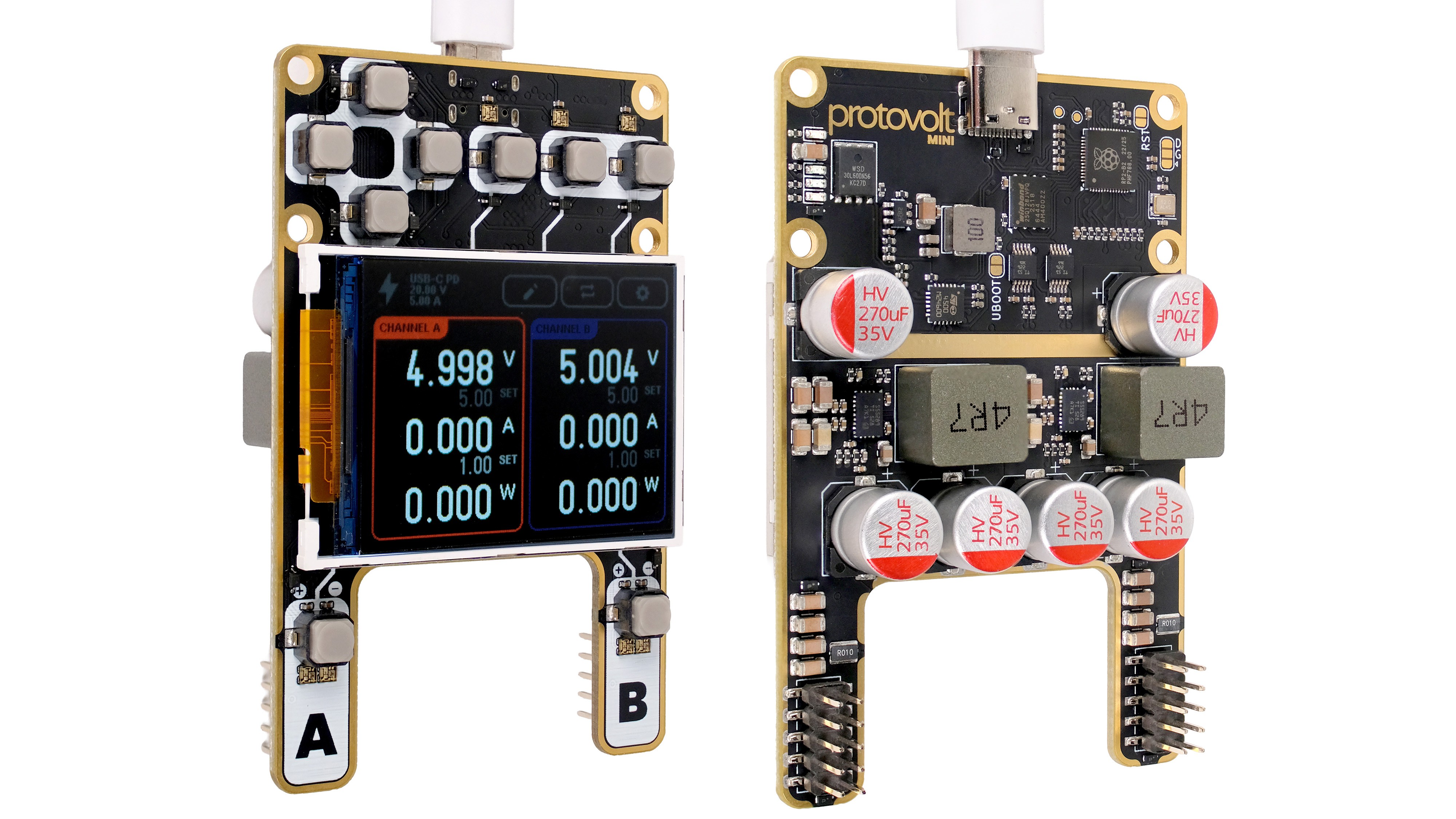
Front and back of a ProtoV MINI, supplying 5V power into both outputs.
Next up: more software development. I'm thinking an API in Python, so that multiple devices can be controlled directly via a host computer. This will allow for the running of long term power tests for professionals, battery charging cycle monitoring, and general lab activites in an educational setting. Also, more hardware revisions as EMI/noise analyses come in. I'll post some transient scope traces, and some FFT noise graphs as midterms roll into finals.
I'd love to hear feedback on the UI flow, and voltage/current control features before the final release. If you've got experience with USB-C PD and noice, I'd also be really open to compare notes, and to open up discussions on the engineering front.
Take a look at the Github, and sign up for updates on CrowdSupply!
- Alex Xia
(Sitting in warmth talking about USB-C PD while the first snow came in Montreal.)