 zpekic
If Basic CPU was a real IC (maybe one day it will be? :-)) the data sheet would brag the following features:
- Fully static design - clock frequency from 0 (single step) to 100MHz
- 64k addressable memory for Basic program and data
- Up to 2k of code memory, on separate bus from Basic program and data
- Microcontroller features with internal RAM, and 2 parallel 8-bit ports
- Easy interfacing with popular serial and parallel consoles using built-in ports
- Memory-mapped I/O allowing simple interfacing with most popular peripheral chips and devices
- Ability to execute Basic program from EPROM/ROM for embedded applications (no RAM needed)
- Built-in separate serial port for program execution tracing and debugging
- Fast execution due to separated program, data and return stacks and GOTO/GOSUB target caching
- 16-bit, 2's complement binary arithmetic capable of multiplication in 3.5 microseconds and division in 7 microseconds at 4MHz system clock
- State of art micro-coded architecture for future improvements and upgrades
CPU has "Harvard architecture" - its program (IL code) and data (Basic statements and command line) reside in two independent memory stores. Typically, the former is ROM, latter is RAM, but both can be ROM.
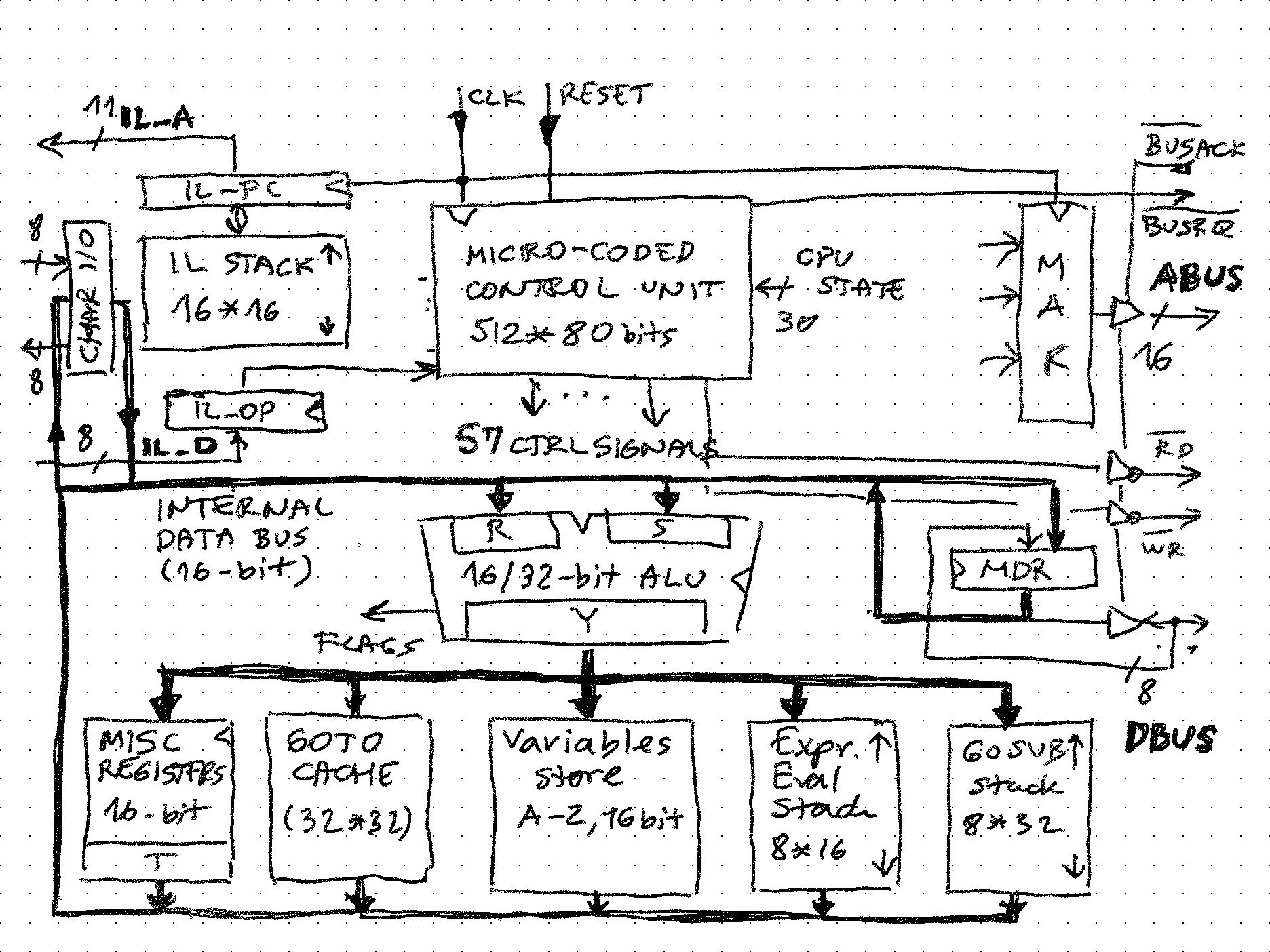
Here is an improvised sketch of the main CPU components:
Implementation is mostly in one VHDL source file (may refactor later), with few subcomponents:
- Serial tracer is not needed for the CPU operation but is extremely useful to observe its operation which helps with debugging
- Binary to BCD conversion uses BCD adders, unlike rest of the CPU which is binary 2's complement, so it makes sense to separate it out.

Main components (some may merit separate project logs, stay tuned)
Micro-coded control unit.
(if not familiar with micro-coding, this project goes into some details, including the MCC compiler and the toolchain)
Consists of:
- Horizontal microcode store 512 words deep and 80 bits wide. 23 bits are consumed by the control unit (5 for IF, 9 for THEN and 9 for ELSE), 57 remaining lines control every other component of the CPU
- Mapping ROM that translated IL op codes to microcode routine start. This is 256 words deep, 9 wide.
- Control unit which has 9-bit wide microinstruction program counter and 4 level deep stack.
- 32 conditions (5-bit selection) conditions about the state of the CPU and external signals are used to control the microprogram flow.
All of these components are automatically generated by running the 2-pass MCC compiler on the microcode source file. Deep dive into details of micro-coded control here.
Code processing components.
Consist of:
- IL_PC - 11-bit program counter which is directly exposed outside of the CPU to address the store containing the TBIL store. It can be loaded from 7 different sources, including the IL stack, but like most typical program counters, it is incremented during instruction fetch
- IL_OP - 8-bit instruction register, loaded directly from TBIL store, which is its only source. Used by microcode controller to drive the mapper store, but also to contain offsets of various branch and jump instructions.
- RetStack and RetSP - 16 level deep stack, 16-bits wide (only 11 are used) and its 4-bit wide stack pointer. All stacks inside the CPU "grow down" (towards increasing value of SP) and in all SP points to first free location. The advantage of this is easy checking of full / empty / count of used stack locations.
Input / output.
- CHARIN - 8-bit input register. External hardware must present a valid ASCII code at this input and raise the "inchar_ready" signal. This signal is then used in microcode to detect and act on incoming character. Main cases are during execution of GL (get line) instruction, and to check for the BREAK character (ASCII code 0x03). It can be compared with direct value specified by microinstruction to determine which character and act accordingly.
- CHAROUT - 8-bit output register. It is exposed to external hardware (e.g. console), which is supposed to watch the "outchar_send" signal to process it and raise "outchar_ready" to indicate it has processed it. If outchar_ready is not raised, the CPU will wait indefinitely on the outside hardware. For example, at CPU clock of 100MHz it takes 26000 cycles in wait loop for each character sent. CHAROUT register also has some interesting capabilities:
- Each character sent increments the TAB counter, or if it is CR resets it to zero
- Allows "escaping". If ^ is detected, next character is interpreted as an ASCII control code. This way it is easy to send ^G (bell), ^M (CR/Enter) and other codes. ^^ is needed to send the caret symbol.
- Allows leading zero suppression. If sending 0 is detected, it is "swallowed" unless the previous character was a non-zero digit. The digit is coming from most significant nibble of the Y register, and the 4-bit value is automatically converted to ASCII 0...9 using a 16*8 lookup table.
ALU.
This component merits own project log because it is fairly complex. It has state (registers R, S, Y and some flags) which allows it to execute stateful operations (e.g. division, BCD to binary and binary to BCD conversions, loading of consecutive 8-bit values into 16-bit etc.
Data processing components.
Basic code (statements) and Basic command line are data for this CPU. This data store can be up to 64k bytes. The memory map is as follows:
- Basic input line - 0x0000 to 0x007F - total of 128 characters
- Basic program - 0x0080 to 0xFFFF - total of 65408 characters
This memory ("core" in some of the Tiny Basic documents) can be accessed from Basic program using USR function which exposes PEEK/POKE functionality. A part of this memory can be reserved for I/O devices (memory mapped I/O in 6502 style)
Main components:
- MAR - 16-bit memory address register. Output is driving the ABUS address bus through 3-state drivers. Only when /BUSACK input signal is low, can the CPU execute a read or write operation.
- MDR - bidirectional 8-bit data register. One of the input MUX sources is connected to DBUS, and output drives DBUS only in the same /BUSACK case. Various condition codes are driven by the value in MDR, for example if byte here is upper- or lower-case ASCII, numeric etc. It also supports conversion to upper case as one of its MUX inputs. This is how "Print" and "priNT" will both work.
- /RD and /WR signals. These come directly from the micro-code fields. If either is low, /BUSREQ output is asserted to indicate the desire to access the core memory. These are also 3-state, so external device can completely take over the memory and keep it as long as needed by holding /BUSACK high. There is no /WAIT input signal (Z80-style), but /BUSACK can be used for that purpose too.
Variables
This is a simple store of 32 entries, each 16 bits. Variable A is mapped to location 1, up to Z, leaving a few unused. Within this component, there is also a "vars_index" 5-bit address register which can be loaded from byte at the stack top (as it contains the ASCII code, 64 is subtracted to form the correct address in the store). The value of variable can come only through T register which can get it from multiple sources:
 update_Vars: process(clk, mb_Vars)
 begin
    if (rising_edge(clk)) then
        case mb_Vars is
--            when Vars_same =>
--                Vars <= Vars;
            when Vars_indexFromExpStack =>
                -- top byte on expressions stack (ExpSTLo) contains twice the upper - case ASCII code of the variable name
                vars_index <= std_logic_vector(unsigned('0' & ExpSTLo(7 downto 1)) - X"40");
            when Vars_T =>
                Vars(to_integer(unsigned(vars_index(4 downto 0)))) <= T;
            when others =>
                null;
        end case;
 end if;
 end process;
while writing this, I looked at the implementation of SV (store variable) instruction:
////////////////////////////////////////////////////////////////////////////////
.map 0x13;                                    // SV (Store Variable)
////////////////////////////////////////////////////////////////////////////////
traceString 37;                                // trace mnemonic
if STACK_IS_EMPTY then ESTACK_ERR;
T <= ExpStack, ExpStack <= pop2;        // pop T from stack
if STACK_IS_EMPTY then ESTACK_ERR;
Vars <= indexFromExpStack, ExpStack <= pop1;// pop index (variable name A-Z)
Vars <= T, goto fetch;                // Vars(index) <= T
and realized that 1 clock cycle can be eliminated. Given the frequency of storing variables (each LET statement) this can bring a bit of a perf improvement:
////////////////////////////////////////////////////////////////////////////////
.map 0x13;                                    // SV (Store Variable)
////////////////////////////////////////////////////////////////////////////////
traceString 37;                                // trace mnemonic
if STACK_IS_EMPTY then ESTACK_ERR;
T <= ExpStack, ExpStack <= pop2;        // pop T from stack
Vars <= indexFromExpStack, if STACK_IS_EMPTY then ESTACK_ERR;
ExpStack <= pop1, Vars <= T, goto fetch;    // Vars(index) <= T and remove used stack entry
Expression / evaluation stack.
Used for evaluation of expressions as well as execution of various instructions, such as FV, SV, CP, USR, LS which require the data on the stack be in specific form (e.g. for LS - list, the stack top is end line, stack next is first line to list). It is 16 levels deep, 8-bits wide because some stack operations work on bytes not whole 16-bit words. In order to speed up the 16-bit operations, the actual implementation is a 2-port RAM to be able to read/write 16-bits in one clock cycle.
 -- Stack top value
 ExpSTHi <= ExpStack(to_integer(unsigned(ExpSP) - 2));
 ExpSTLo <= ExpStack(to_integer(unsigned(ExpSP) - 1));
GOSUB stack.
8-levels deep, 32-bits wide. Making it 32 - bit instead of 16 like in other implementations helps performance because both Lino (line number of the GOSUB caller) and BP (Basic Pointer location of the caller statement) are saved, so when RETURN is executed no search in the Basic code is needed, everything needed to resume execution on the caller level is ready.
////////////////////////////////////////////////////////////////////////////////
.map 0x14;            // GS (GoSub - save Basic line for RETURN later)
////////////////////////////////////////////////////////////////////////////////
traceString 47;            // Trace mnemonic
if IS_RUNMODE then next else INTERNAL_ERR;
if STACK_IS_FULL then BSTACK_ERR;
BasStack <= push_Lino_and_BP, goto fetch;

////////////////////////////////////////////////////////////////////////////////
.map 0x15;            // RS (ReStore saved line - Basic RETURN)
////////////////////////////////////////////////////////////////////////////////
traceString 48;            // Trace mnemonic
if IS_RUNMODE then next else INTERNAL_ERR;
T <= BasStack_Hi,if STACK_IS_EMPTY then BSTACK_ERR;
Lino <= T, T <= BasStack_Lo;
BP <= T, BasStack <= pop, goto fetch;
Miscellaneous registers.
16-bit registers that hold important state needed to execute TBIL code and interpret Basic:
- T - internal data path hub that can load data from almost every other location in the CPU, and is the source for other registers and components. This way in 2 cycles data can go from any point to point, while saving on width of microinstruction (which is already high at 80 bits) as otherwise all n * m combinations would need to be translated into microinstruction word bits. It can also increment, decrement and load result of logical operations hooked up behind USR().
- BP and SvPt - Basic Pointer points to character in core memory which is examined to interpret it (as a keyword, variable, value etc.). During program execution BP points to the Basic program (0x0080..0xFFFF) but when INPUT is executed, parsing must go to input buffer so SvPt (save pointer) is used during that time to preserve it.
- LS and LE (Line Start, Line End) - helpers to isolate the statement line in Basic program which will be removed or replaced during IL (insert line) instruction
- BE - Basic End pointer - also used in IL to know which is the last character of the new line being inserted. If BE=BP it means that line must be deleted as it number has been entered without any content.
- PrgEnd - points to the 2nd on 2 NULL bytes that indicate end of Basic program. This pointer is important when deleting or inserting lines into Basic because the memory copy operations run to this pointer, allowing the end of program to shrink / grow as needed.
- Lino - line number of currently executing line, if in run mode, or 0 if CPU is in command mode. Some instructions also stage in this register the line number of next statement to be executed (see NX - next statement implementation in microcode)
- XQhere - stores the address of the XQ instruction in the IL store. This allows instructions such as GO, NX to start executing at the beginning of the statement interpreter and not at 0, which is the start of the command mode.
GOTO cache.
This is the key to Basic CPU performance because (depending on size and complexity of Basic program in core memory) speeds up execution 2+ times.
Basic statements in core memory are stored in consecutive order. To find a statement (GOTO, GOSUB) it is necessary to traverse the memory from the beginning (from location 0x0080 onwards) and look for the 2-byte binary representation of the destination line number. Once the location of that instruction is found, it is stored in this cache, indexed by its line number. Up to 32 locations can be cached, and cache hit saves lots of searching time. The cache is initialized to all entries free when going from command to run mode (Lino changing from 0 to !=0). Stay tuned for separate project log about the structure and operation of this cache.
Discussions
Become a Hackaday.io Member
Create an account to leave a comment. Already have an account? Log In.