 zpekic
What would a CPU project be without a "Hello World" demo? :-)
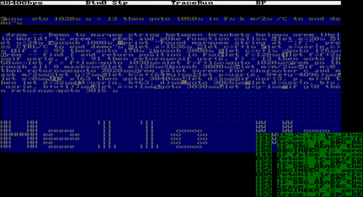
I originally introduced VGA display as a debugging tool to visualize content of Basic input line and program (esp. GL and IL instructions), as described here. But once display surface exists, why not use it as simple text-based screen output?
Tiny Basic system currently implements 2k RAM mapped to address space 0x0000 to 0x07FF. If the program is shorter than that, whatever remains can be used as "window" for example 8*64 in size, starting at RAM location 0x0600 or 1536 decimal.
For the demo to work, 2 additional capabilities were needed:
- Ability to access Basic RAM (classic PEEK and POKE)
- Ability to read the font definition for the characters in the scroll, and "magnify" them by 8X so that 8*8 pixel becomes 8*8 character.
Memory mapping
Total Basic memory space is 64k, leaving 62k open in the system. I used the top 4k to access same character generator ROM VGA controller uses (two copies of this ROM are now in the design). This char gen has 8*8 font similar to C64, but I also added representation of control characters 0x00-0x1F which help with debugging (note CR in memory display above after each Basic statement). From the outside, the char gen appears to hold 256 characters, but the capacity is only 1k, ASCII codes 0x80..0xFF are inverse duplicates of 0x00..0x7F.
sel_hi4k <= '1' when (A(15 downto 12) = X"F") else '0';
memData <= pattern when (sel_hi4k = '1') else ram(to_integer(unsigned(A(10 downto 0))));
D <= memData when ((nBUSACK or nRD) = '0') else "ZZZZZZZZ";

-- Character generator ROM handy for the marquee demo
chargen: entity work.chargen_rom port map
(
    a => A(10 downto 0),    -- 256 chars (128 duplicated, upper 128 reversed) * 8 bytes per char
    pattern => pattern
);
USR() function
The original Tiny Basic ran on a number of microprocessors from 1970ies/80ies. To allow extensibility, each implementation of TBIL interpreter was supposed to define and implement the r = USR(a, p1, p2) call from Tiny Basic, where:
- a - address of the native (assembler / machine code) routine to call
- p1 - required parameter
- p2 - optional parameter
- r - result
All of the above were 16-bit values. For example:
| argument \ CPU | 6502 | 6800 | 1802 |
|---|---|---|---|
| a | JSR a | JSR a | R3=a, P=3, X=2 |
| p1 | MSB=X, LSB=Y (to be verified!) | X (16-bit) | R8 |
| p2 | A | A | RA |
| r | MSB=A, LSB=Y, RTS to return | A, RTS to return | MSB=RA.1, LSB=D, SEP 5 to return |
At minimum, implementing PEEK / POKE was expected, but any other (such as direct reading of keyboard etc.) was possible. Only option for Basic CPU was to implement in microcode some of the most useful USR calls, and these are also used in the Scroll demo Basic program.
Currently implemented:
| Function | a | p1 | p2 | r | used in demo? |
|---|---|---|---|---|---|
| Logical | 0 .. 7 | 16-bit word | 16-bit word | p1 op p2 | a = 3, which is logic AND operation |
| PEEK8 | 20 | address of byte to update | N/A | M[a] | yes |
| PEEK16 | 21 | address of word (on any byte boundary) | N/A | 256*M[a]+M[a+1] | no |
| POKE8 | 24 | address of byte | 8-bit value to write to memory addressed by a (upper 8-bit of the value is ignored) | p2 | yes |
| POKE16 | 25 | address of word (on any byte boundary) | 16-bit value to be written to a in big endian representation | p2 | no |
To save on the "switch" statement that would take precious microcode, all binary logic operations are implemented with the same expression, controlled by 3 lowest bits of parameter a.
(omitted)
when T_binop =>
    -- S    operation
    -- 0    T NOR R
    -- 1    T NOR /R
    -- 2     /T NOR R
    -- 3    T AND R
    -- 4    T OR S
    -- 5    T OR /S
    -- 6    /T OR S
    -- 7    T NAND R
    T <= S2 xor ((S1 xor T) nor (S0 xor R));
(omitted)

-- masks for T_binop
S0 <= (others => S(0));
S1 <= (others => S(1));
S2 <= (others => S(2));
Discussions
Become a Hackaday.io Member
Create an account to leave a comment. Already have an account? Log In.