 zpekic
TL;DR
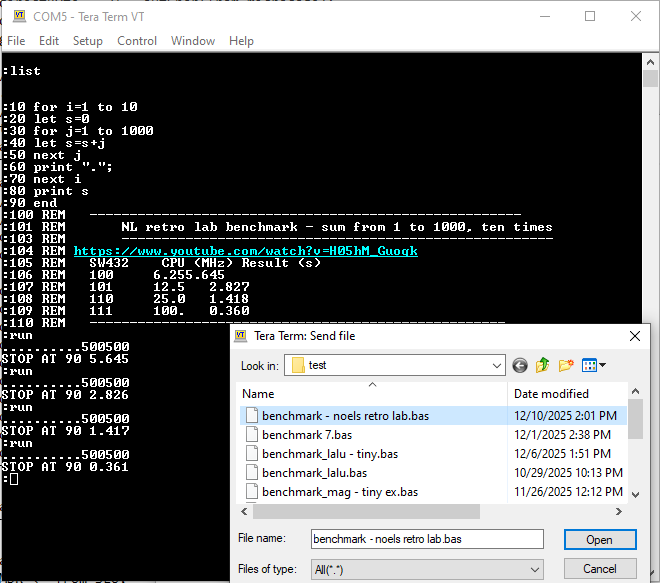
I extended the CPU from 16 to 32 bits to specifically run the following benchmark, proposed by Noel's Retro Lab:
I was most interested how 32-bit Basic CPU is performing relative to modern "retro" computers. They have fixed CPU clock, so I adjusted or interpolated results from runs seen above for comparison:
| System / CPU | CPU clock (MHz) | time (s) - quoted from here | Basic CPU time (s) | relative performance |
| ZX Spectrum Next / Z80 | 28 | 5 | 1.27 | 3.94 |
| Agon Light / eZ80F92 | 18.432 | 1.8 | 1.05 | 1.71 |
| Mega 65 / GS4510 | 40.5 | 1.047 | 0.88 | 1.19 |
While these numbers favor the Basic CPU, in reality the systems above can run much more feature rich variants of Basic, with graphics, sounds, functions etc. while Basic CPU has only USR/PEEK/POKE at disposal. Still, not too bad for running an interpreter from 50 years ago on FPGA from 10 years ago.
Extending from 16 to 32 bits
Most Basic variants support to 16-bit 2's complement integers. They are fine for many use cases, and arithmetic with them is reasonably fast even on 8-bit CPUs. Unfortunately, Tiny Basic has no Floating point support, so having just 16-bit integer can be limiting. So I decided to expand the CPU from 16 to 32-bits. The design goals were:
- No changes to the interpreter - both original and extended interpreters can run on 16 and 32 versions
- Minimal changes to microcode - only where absolutely needed, for example 32-bit 2's complement integer convert to up to 10 decimal digits, while 16-bit to 6 so some loop counters etc. must be changed
- Changes to hardware are ok, but avoid any special case if/then if possible
For #3, there were two possibilities:
- Run-time support for 16/32 bit switch. A bit like 65802 vs 65C02 - a flag or a pin flips the CPU to 32-bit mode.
- Build-time support for 16/32 bit generation of the CPU itself.
I chose #2 as it seemed as easier implementation, and also because if I continue this project it is unlikely I would go back to 16 bit (next logical step is implementing Floating Point, which is viable only on 32-bit data / variables), and in that case all the complexities of supporting 16/32 will be present in the CPU, bloating the FPGA footprint and won't be needed right after boot into 32-bit mode.
Parametric VHDL design
The general idea here is to use feature of hardware description language to generate the registers and interconnections using parameters consumed during compile time. This code handles about 80% of what is needed to compile the design to be either 16 or 32 bit CPU:
-- generics
constant MSB_DOUBLE: positive := (MSB + 1) * 2 - 1;                            -- 31 / 63
constant MSB_HALF: positive := (MSB + 1) / 2 - 1;                                -- 7 / 15
constant ZERO: std_logic_vector(MSB downto 0) := (others => '0');            -- X"0000" / X"00000000"
constant MINUS_ONE: std_logic_vector(MSB downto 0) := (others => '1');    -- X"FFFF" / X"FFFFFFFF"
constant BITCNT: std_logic_vector(4 downto 0) := std_logic_vector(to_unsigned(MSB, 5));        -- 15 / 31
alias IS_CPU32: std_logic is BITCNT(4);                                                                        -- '0' / '1'
constant STEPCNT: std_logic_vector(7 downto 0) := std_logic_vector(to_unsigned(MSB + 1, 8)); -- X"10" / X"20"
constant BCDDIGITS: positive := (MSB + 9) / 4;     -- 6 / 10
constant CP_OFF: positive := MSB_HALF + 1;        -- 8 / 16
type ram16xHalf is array (0 to 15) of std_logic_vector(MSB_HALF downto 0);
type ram32xFull is array (0 to 31) of std_logic_vector(MSB downto 0);
During build-time, parameter MSB is passed in as either 15 or 31, and then based on that various other values are determined, for example BITCNT which determines the number of steps during division, etc.
The above is not sufficient to create a functioning 32-bit CPU. The main problem is that the memory interface toward RAM that holds Basic code and input line remains 16 bit address / 8 bit data (64kb RAM), Basic line numbers are still meaningful only to 16 bits (due to the convention how Basic lines are stored) etc. The table below summarizes the major differences that had to be addressed with generating the 32 vs. 16-bit CPU.
| Component / design area | 16-bit | 32-bit |
| Variables A-Z | 48-bits per variable: 16 for value 16 for FOR (line number of corresponding NEXT) 16 for NEXT (line number of corresponding FOR) | 64-bits per variable, FOR/NEXT are still 16, value is 32 |
| Basic return stack | 8 entries, 16 bits each | 16 entries, 16 bit each (I just decided to make the stack deeper for both versions and align to other stack depths which are all 16 levels) |
| IL return stack | 16 entries, 11-bits | No change |
| Evaluation stack | 16 entries, 8 bits, which can also be accessed as 8 entries 16 bits | Doubled in width. Following instructions now work differently: LB nn - now pushes 16-bits 0x00nn to stack, not just byte nn LN nnnn - now pushes 32-bits 0x0000nnnn to stack, not 16-bits Setting the upper bits to 0 works because literal values are always used by interpreter with meaning of "positive integer". The other option would have been to sign extend based on bit 7 or 15 of literal value (e.g. LB 0xAF would push 0xFFAF to stack) |
| ALU - register R | 16-bits | 32-bits. Checking for zero value of R had to split. When used in division / modulo as 32 bits divisor, all 32 bits must be checked for 0 (divide by zero error check), and in all other cases it is a counter or accumulates bytes read from Basic RAM, for example Line Number. In those cases zero check must remain 16 bit:
r_is_zero <= r_is_zero_full when (IL_OP = OP_DV) else r_is_zero_16;

...

-- for divide instruction check full R to prevent divide by 0, for other operations R is memory address or line number (16 bit)
r_is_zero_full <=     '1' when (R = ZERO) else '0';
r_is_zero_16 <=        '1' when (R(15 downto 0) = X"0000") else '0';
Note that constant ZERO is parametric too, a vector of either 16 or 32 zeros. |
| ALU register S | 16-bits | 32-bits. A number of memory copy / search operations use S (and also R) registers. For those ALU operations upper 16 bits are cleared to ensure comparisons and counts work. Magic of VHDL ensures this is not a build break:
R(MSB downto 16) <= (others => '0');
Evaluation proceeds from left to right - 15 downto 16 is NIL, which means that "others" (which is effectively an ordered list of connections) is an empty set, causing the whole statement to be NOP for 16-bit CPU, while for 32-bit it is equivalent to setting bits 31 downto 16 (upper word) to 0x0000 |
| ALU register Y | 32-bit (or 8 BCD digits) | 64-bits (or 16 BCD digits). This is mainly the ALU output register and for MUL and DIV it must be double sized. For MUL n*n needs 2n digits, and for DIV upper half contains the remainder, lower the quotient. Other important use is to accumulate the BCD conversion of the value in register R, so it is connected to BCD converter component (see below) |
| Register T | 16-bit | 32-bit. When getting the value from invariably 16 bit registers set the upper word to 0x0000. These source registers include: - internal values such at elapsed time ticks, constants, free memory size etc. - RAM addresses such as BP, PrgStart, LE etc. |
| bin2bcd.vhd | Conversion table 16 entries of 6 BCD digits (24 bits) | Conversion table of 32 entries of 10 BCD digits (40 bits). In addition I had to change the actual BCD adder because at 100MHz, the ripple carry could span reliable 6 BCD digits but not 10. The new BCD adder is much simpler, and is basically the implementation of this classic 6502 patent. S register (step counter) must be initialized with 31 instead of 15. In a serial CPU a completely different BCD conversion circuit / algorithm makes more sense, but in general whenever possible, lookup tables are great way to implement functionality in FPGA. |
| Decimal number output | Microcode: 8 consecutive steps, 7 with zero supression, last 1 without | Microcode: changed to a loop, with counter (register T initialized to 14 (or alternatively, to 6) to pick up 8 or 16 BCD digits from register Y, starting with most significant nibble. Leading zero supression is implemented as a flag "lz" in the ALU, but last iteration of print decimal number ignores this flag. |
| peek / poke byte (USR codes 20, 24) | LS byte of 16-bit register S is used to write, upper 8-bits ignored. For read, LB byte of R is loaded, MSB is 0x00 | upper 24 bits ignored when writing S (poke), or set to 0x000000 for reading R (peek) |
| peek / poke word (USR codes 21, 25) | whole register used S, upper MSB stored in lower address than LSB. Same order read into R | upper 16 bits of register S ignored for write (poke), set to 0x0000 when reading into R (peek) |
| peek / poke double-word (USR codes 22, 26) | poke: register S written twice, consecutively. peek: 4 bytes are read into 16-bit register R, which means that upper word stored is ignored because the lower read of 16-bits overrides it | Lots of big endian fun, similar to MC68008 in which 32-bit values need to be stored into 8-bit memory with MSByte on lowest address. poke: first swap word halves of S register (this is new ALU operation in hardware), store Hi and Lo byte on increasing memory addresses, swap again to get to lower word, again store Hi and Lo. Because USR even for write must return a value onto stack, proceed to peek below, but the address has to be decremented by 3 to point again to the start of the double word in RAM. peek: read byte into register R while shifting it up 8-bits, do this 4 time. |
| Array store @(index) = value | Microcode: call poke16, address evaluated using index2address ALU operation Hardware: index2address multiplies index by 2 as 2 bytes are stored / read | Microcode: check IS_CPU32 flag and call poke32 if true (otherwise poke16) Hardware: index2address now multiplies index by 4, as each array entry is 4 bytes. Of course, this multiplication is done by shifting 2 bit positions left. The base of the array address is PrgEnd + 1 (@(0) starts at first free byte in Basic RAM) -- index offsets for 2 (16-bit) or 4 (32-bit) byte elements
T_offset <= (T(13 downto 0) & "01") when (IS_CPU32 = '1') else (T(14 downto 0) & '1');
|
| Array read var = @(index) | Microcode: call peek16, address evaluation as above | Microcode: check IS_CPU32 flag and call peek32 if true (otherwise peek16) |
Discussions
Become a Hackaday.io Member
Create an account to leave a comment. Already have an account? Log In.