 Mark Rehorst
MY previous table, Arrakis 2.0, has found a new home and that left me in need of a new coffee table. I could go out and buy something fashionable, but I liked having the sand table, so I designed a new one. When the old table was moving to its new home, I managed to break the glass top and had to replace it with a new piece, custom made to fit the oak frame, for $330. I wanted the new table to be a little smaller so it would take up a little less space in my living room and could be easily transported by fitting through doorways, and would use a glass top that would be fast, cheap, and easy to replace. A bit of research led me to 24 x 48" glass that's a common size for coffee tables and available cheaply (about $100 delivered from amazon).
Structure
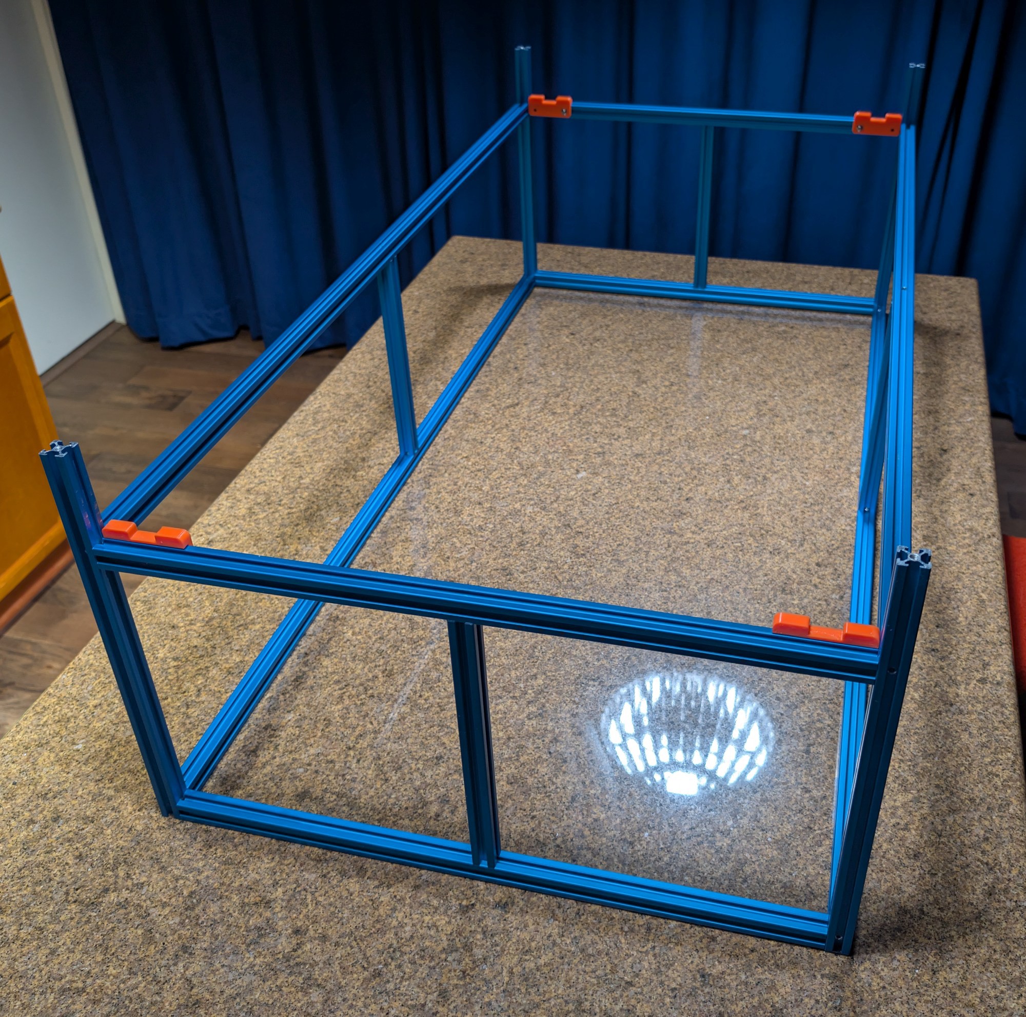
I made a support frame from blue anodized 2020 t-slot.

The sandbox is made using black anodized 2040 v-slot with a 3/16" thick G10 board, covered with white fake leather cloth, fitted into the lower slots of that frame. The upper slots of the long pieces hold RGB LED strips. The sandbox sits on threaded pins in the corners of the support frame. The 2' x 4' glass top just sits on top of the sandbox. I put strips of EPDM rubber weather seal around the top of the sandbox to keep the dust in and spilled drinks out.

The mechanism frame is made from black anodized 2040 v-slot and drops into the support frame, resting on 3D printed spacers that center it in the frame.
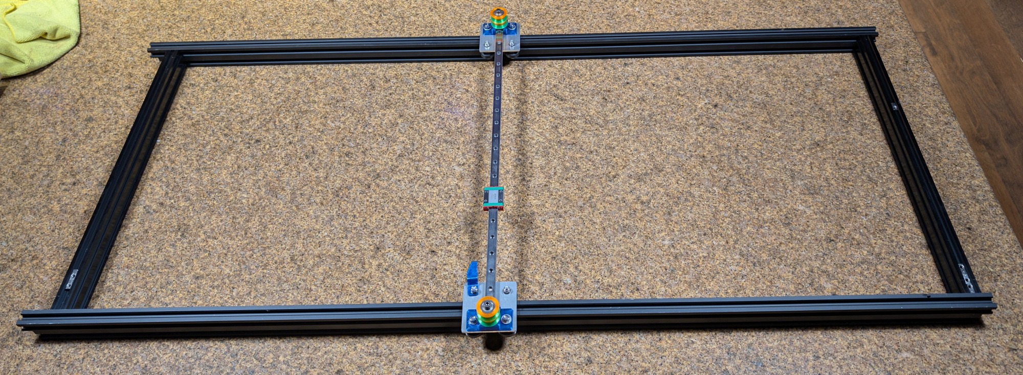


All the t-slot and v-slot pieces were milled square and tapped, and screw directly to each other without any corner braces.
Mechanism
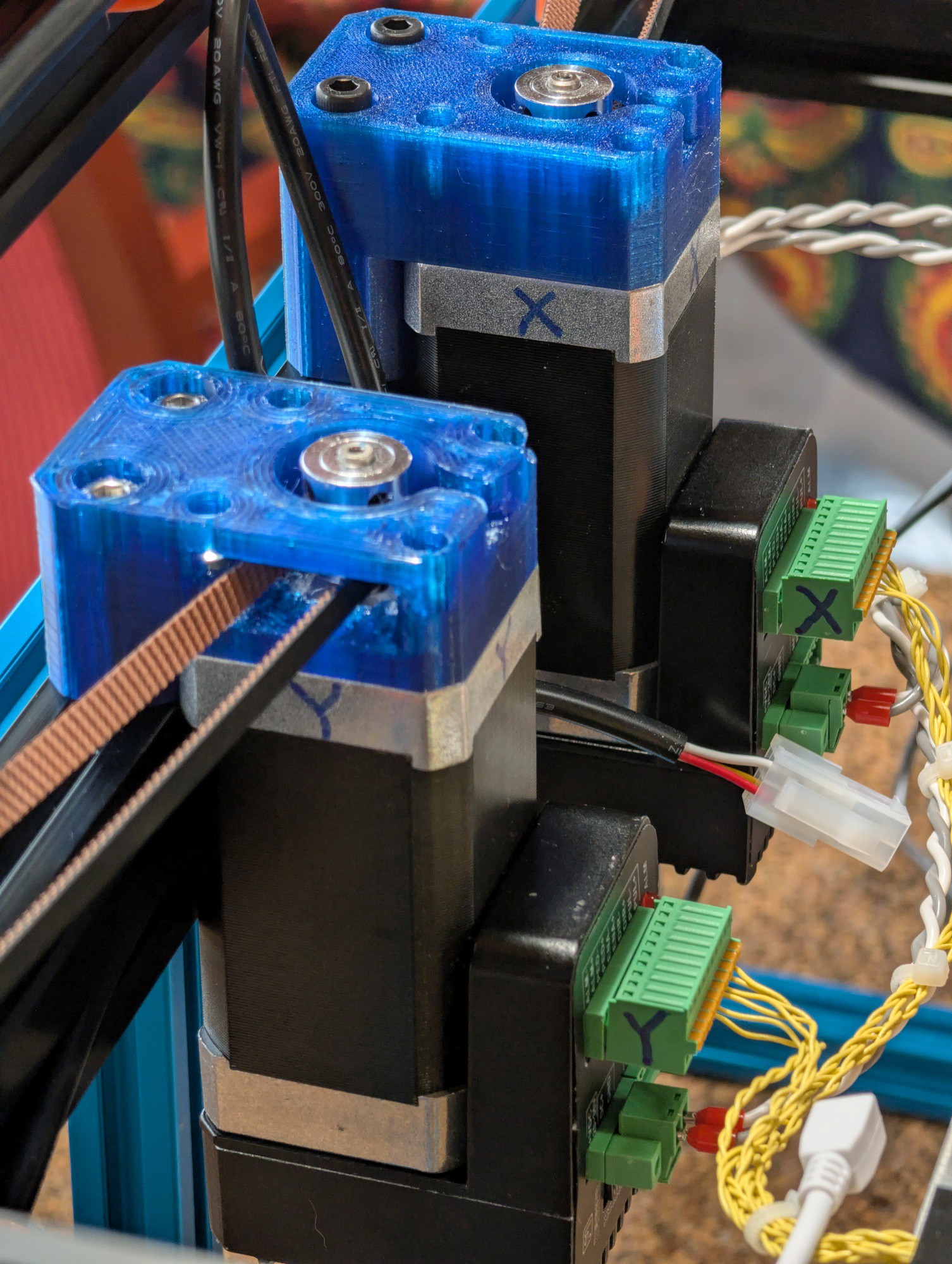
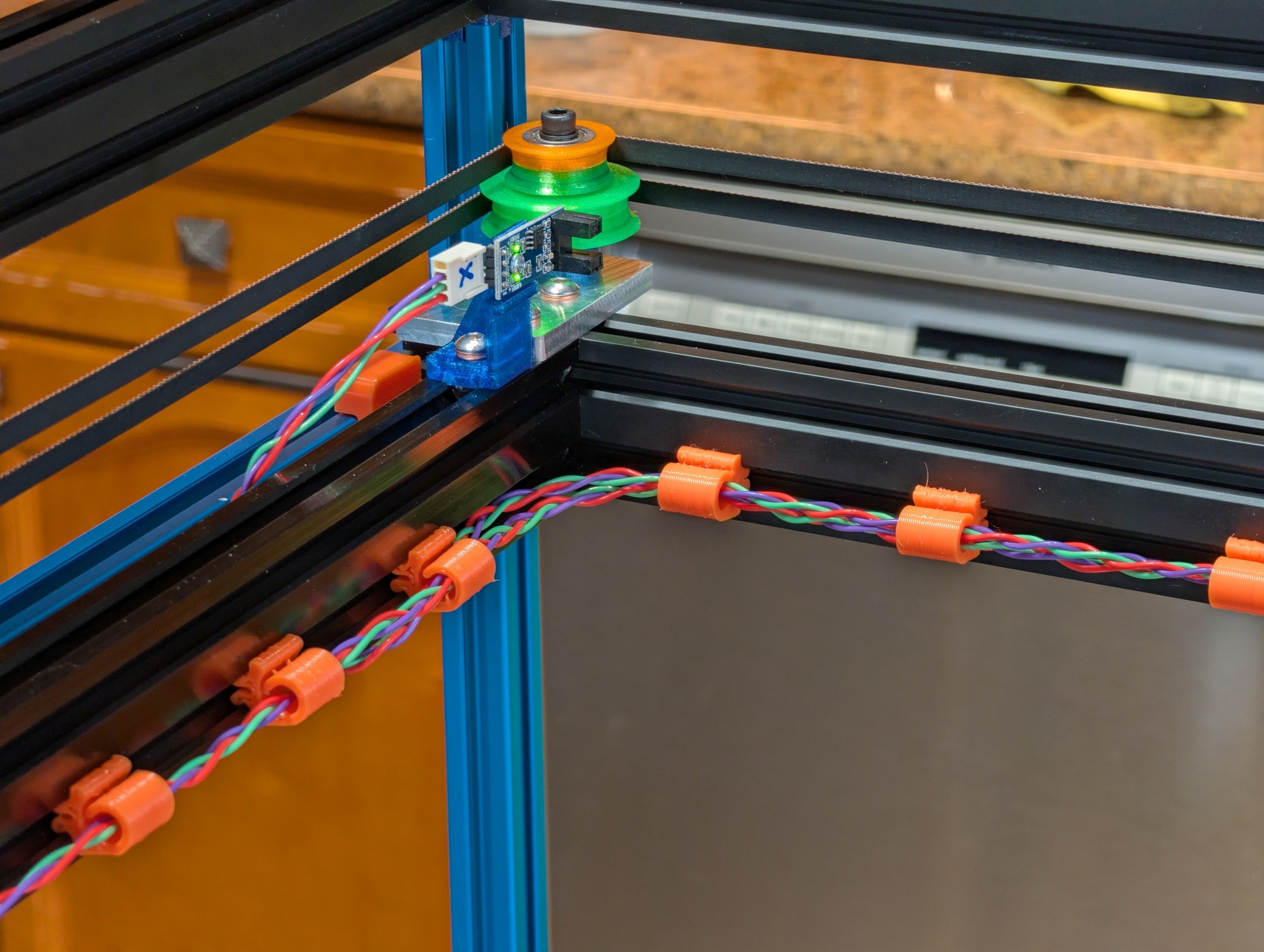
The mechanism is a stacked belt coreXY type driven by cheap, Chinese-made iHSV servomotors with 20 tooth pulleys. Belts are 6mm wide 2GT type commonly used in 3D printers. The motors are mounted on 3D printed mounts at one end of the mechanism frame with a twist in each belt so that the belt teeth touch only the drive pulleys, helping to keep noise down. The idler pulleys are made using stacked F625 bearings in 3D printed concave flanges that prevent the belts from squeaking.
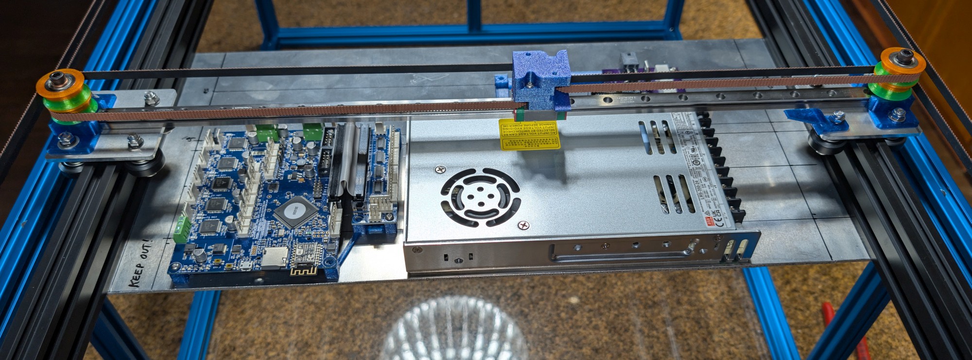
The Y axis (the long one) uses wheeled carriages that roll on the v-slot frame. The X axis is a 12mm linear guide with each end screwed to the wheeled carriages.


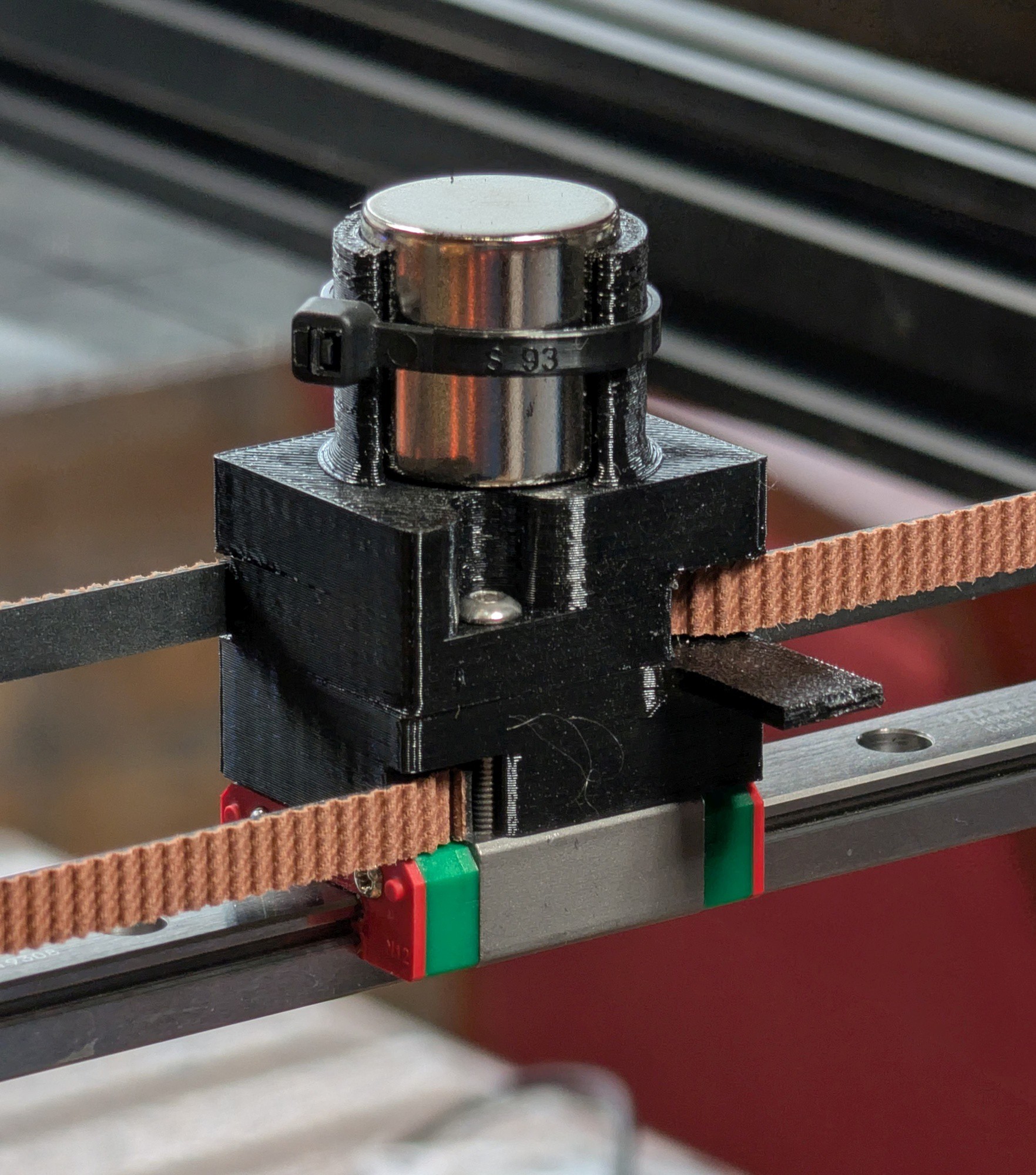
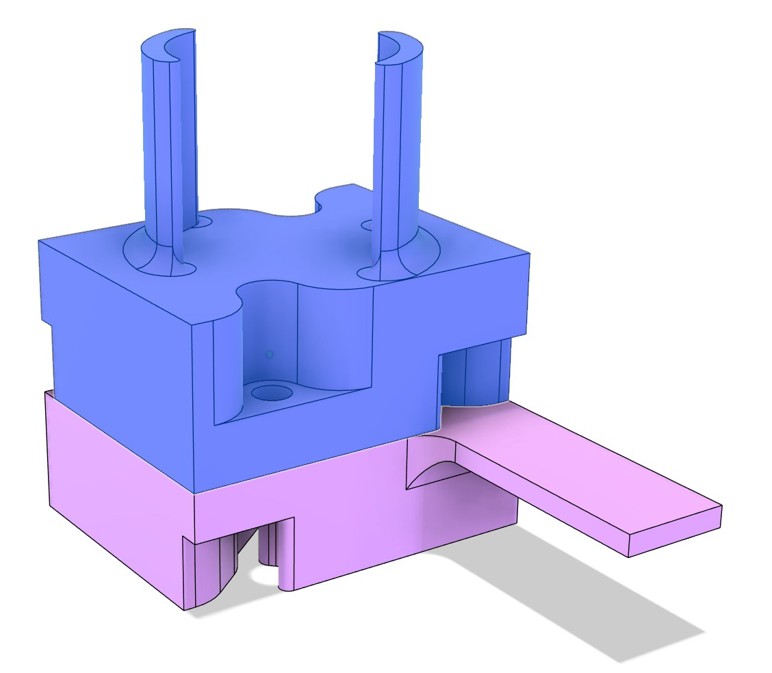
The magnet is a 20 x 20mm cylindrical N52 neodymium type. The magnet carriage/belt clamps are 3D printed parts that screw onto the bearing block on the X axis linear guide. The belt clamps hold the ends of the belts with the teeth interdigitated in narrow slots that don't allow the ends to separate. There is a 3mm air gap between the magnet and the bottom of the sandbox.

Belts are tensioned by sliding the motor mounts along the slots in the frame.
Electronics
Power is provided by a 24V 350W Mean Well switcher. The controller is a Duet3D Duet2 WiFi board with an expansion board that provides step, direction, and enable signals to the servomotors. Endstops are optical type with LM339 comparators and status LEDs onboard. LED strips in the sandbox are powered by a 24-12V buck converter and controlled by their own controller. There are two ReDump protection circuits that sit between the power supply and servomotors. They protect the power supply, controller board, and LEDs against certain types of mechanical/electrical failures at the servomotors.


The Glass Top
I used 2'x4' beveled glass for the top of the table. I painted a black border on the underside that blocks direct view of the LEDs. I'm not sure I like the paint- I don't really trust it not to get scratched or to peel off. Time will tell if it was a bad idea.
11/15/25- I got the LEDs working today and played with the air gap between magnet and the underside of the sandbox. After trying a 12 mm ball and seeing it get left behind by the mechanism, I decided to close the air gap a bit. I stacked two pennies under the magnet, then wrapped the magnet carrier with tape and put a zip tie over the tape to make sure the magnet doesn't lift up.
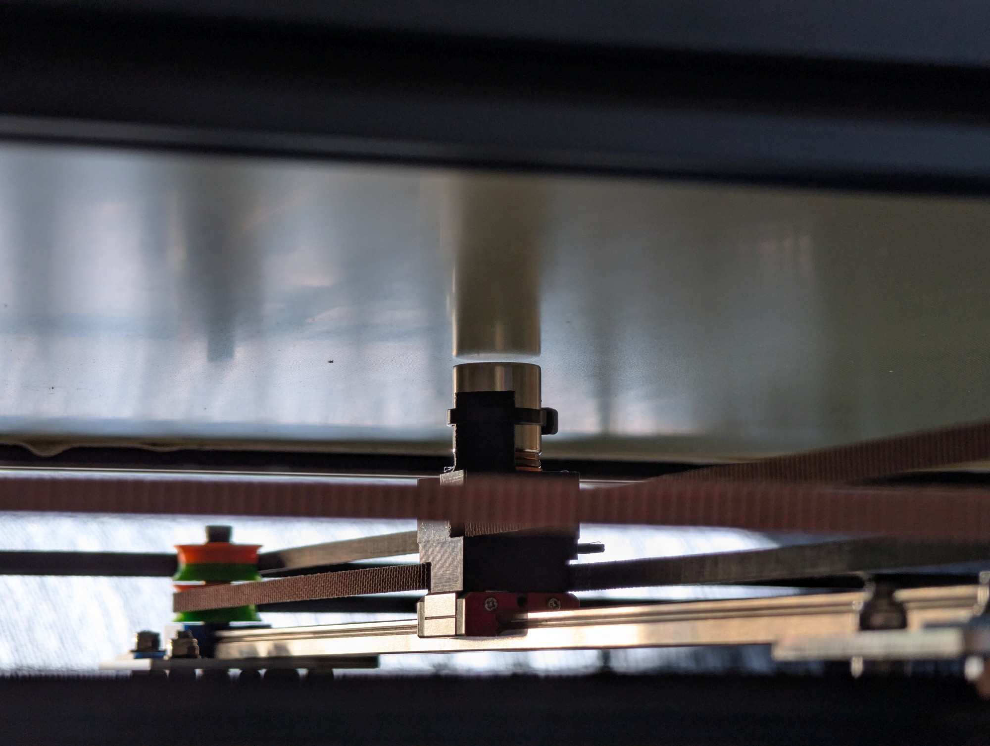
Now a 12 mm ball can be used at 1000 mm/sec and it doesn't get left behind by the mechanism, but I'll probably use a 6mm ball.
The last thing needed to finish it is to wire in the final power cord and switch, and to cut and place the side panels. I have ordered 1/8" light blue mirrored acrylic for that.
11/21/25
I have added floor lighting under the table connecting the LED strips to the strips inside the sandbox
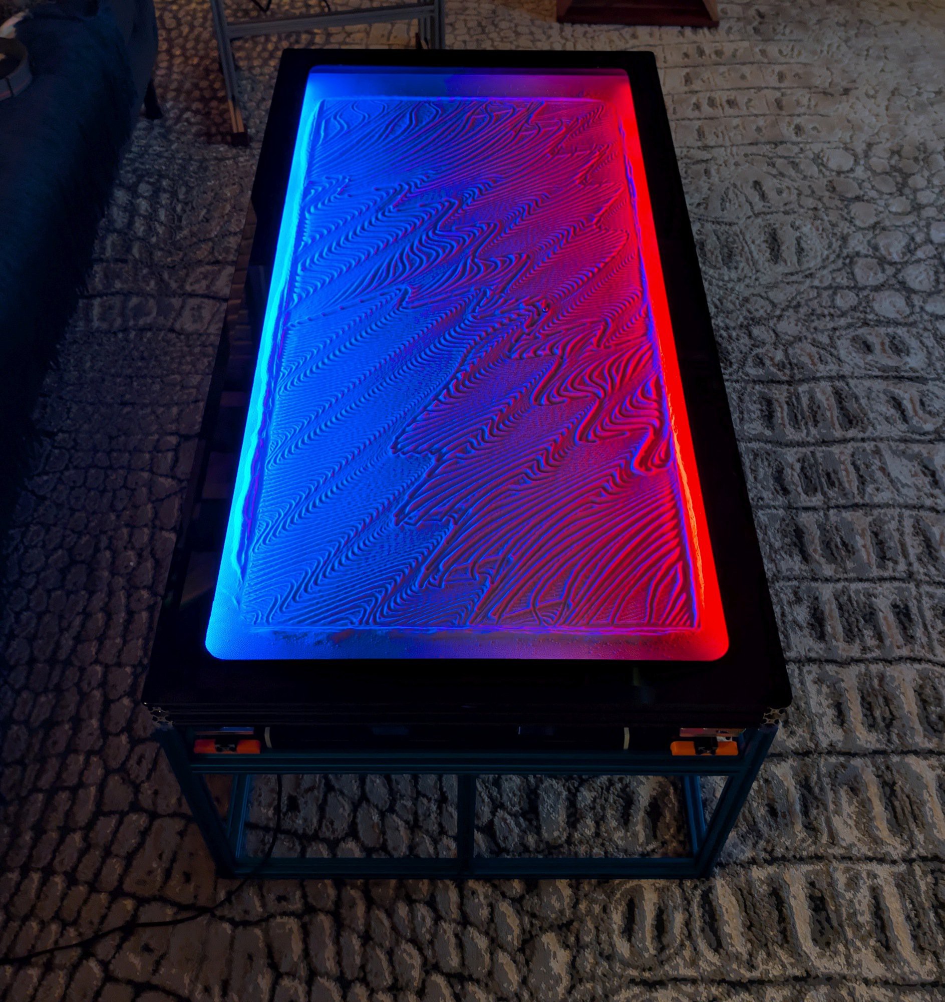
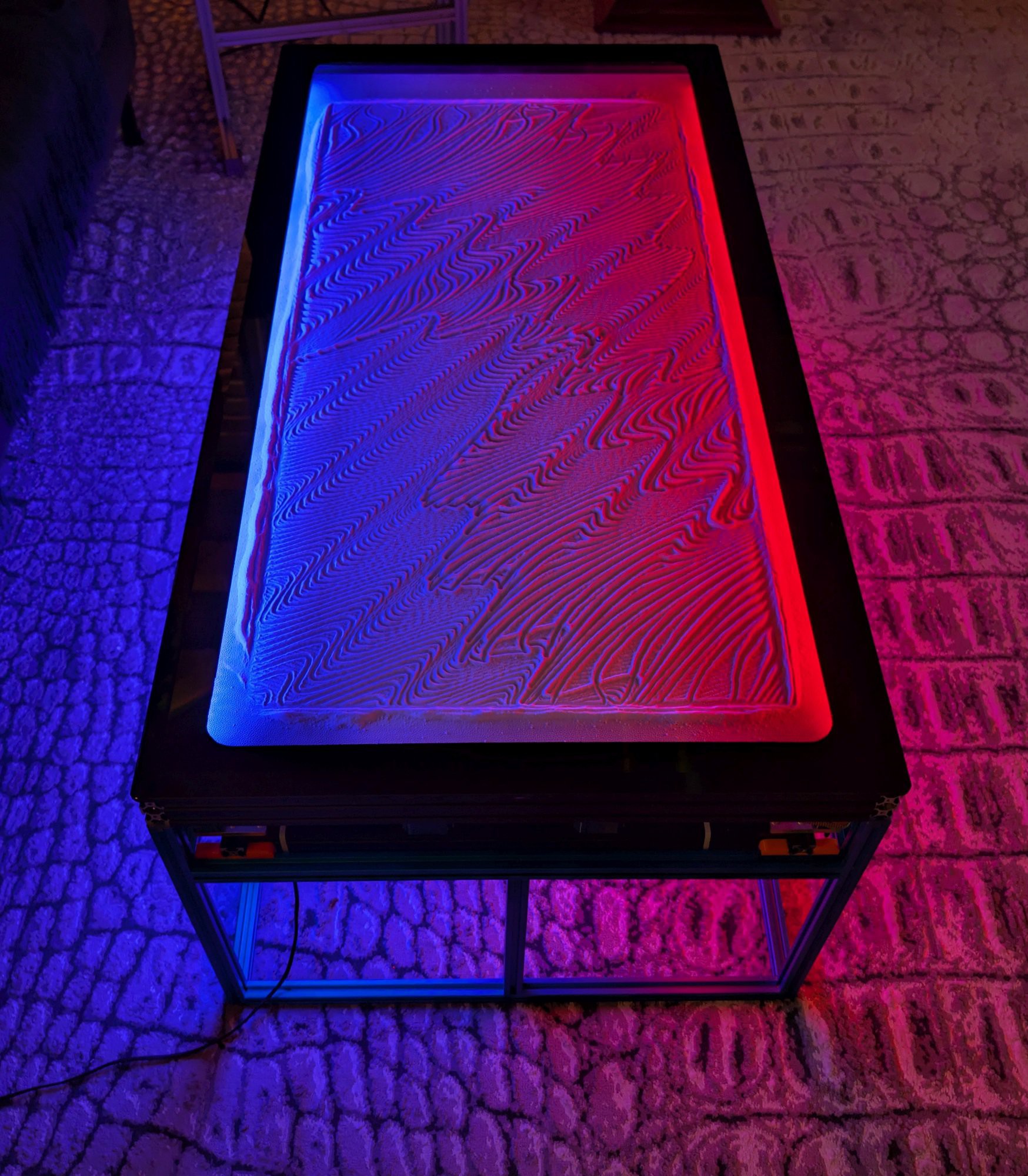
I did some experimenting with Sandify today and found that I can use it to import and scale some pattern files created for Arrakis 2.0 to fit on this table. Unfortunately, it seems to have a file size limitation that causes it to crash with some of the most detailed patterns, so I'm going to have to write a program to scale the patterns myself.
Update 11/22/25
I cut and installed the mirrored blue acrylic side panels today. I used small pieces of clear silicone edging to center the 1/8" panels in the 6.1 mm wide slots in the t- and v-slot. I also added threaded pins to the corner posts of the blue support frame to locate the sandbox and keep it from moving.


This project is officially finished. Now I just have to scale the Arrakis 2.0 pattern files to fit this table...