 Arnov Sharma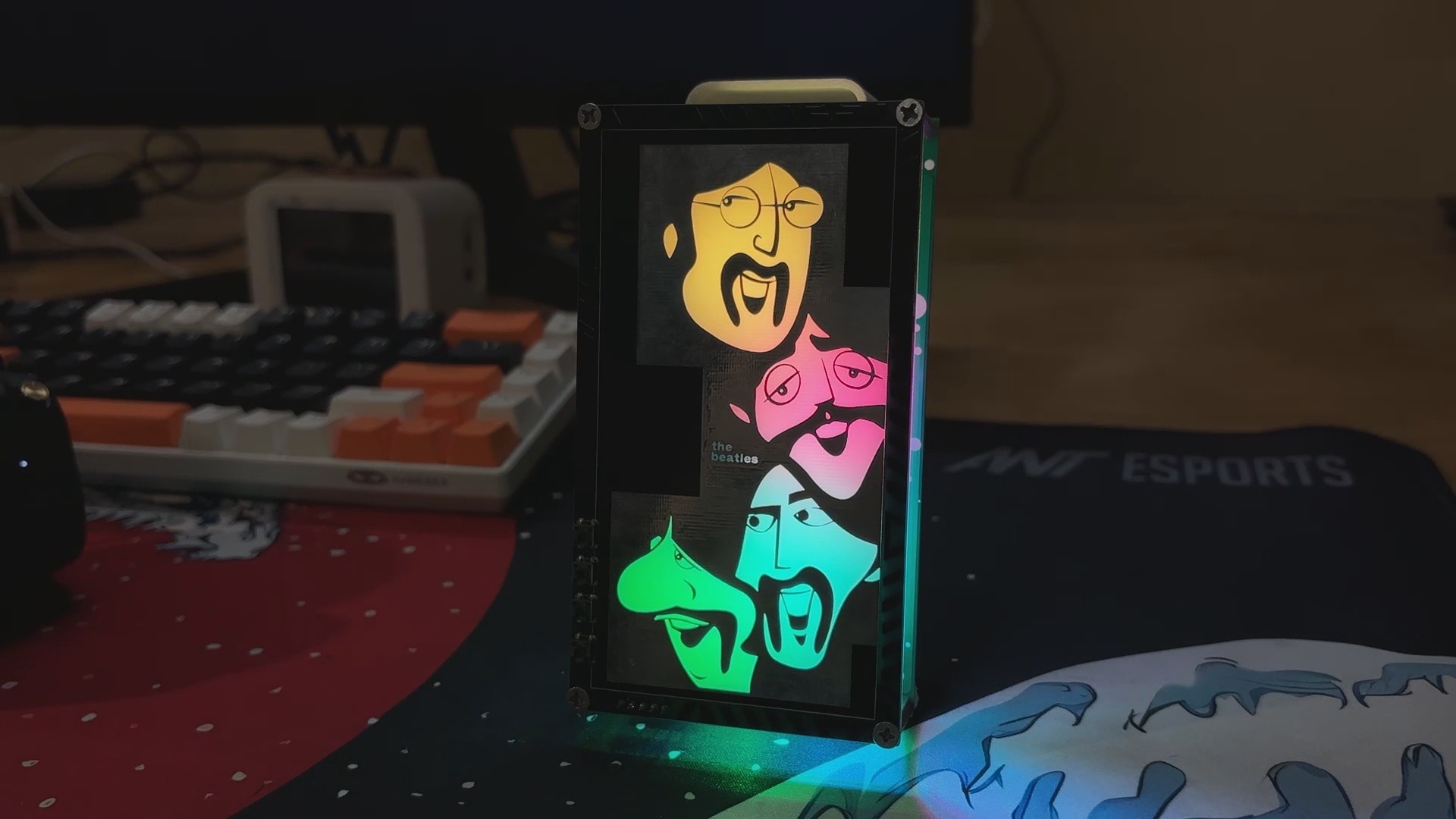
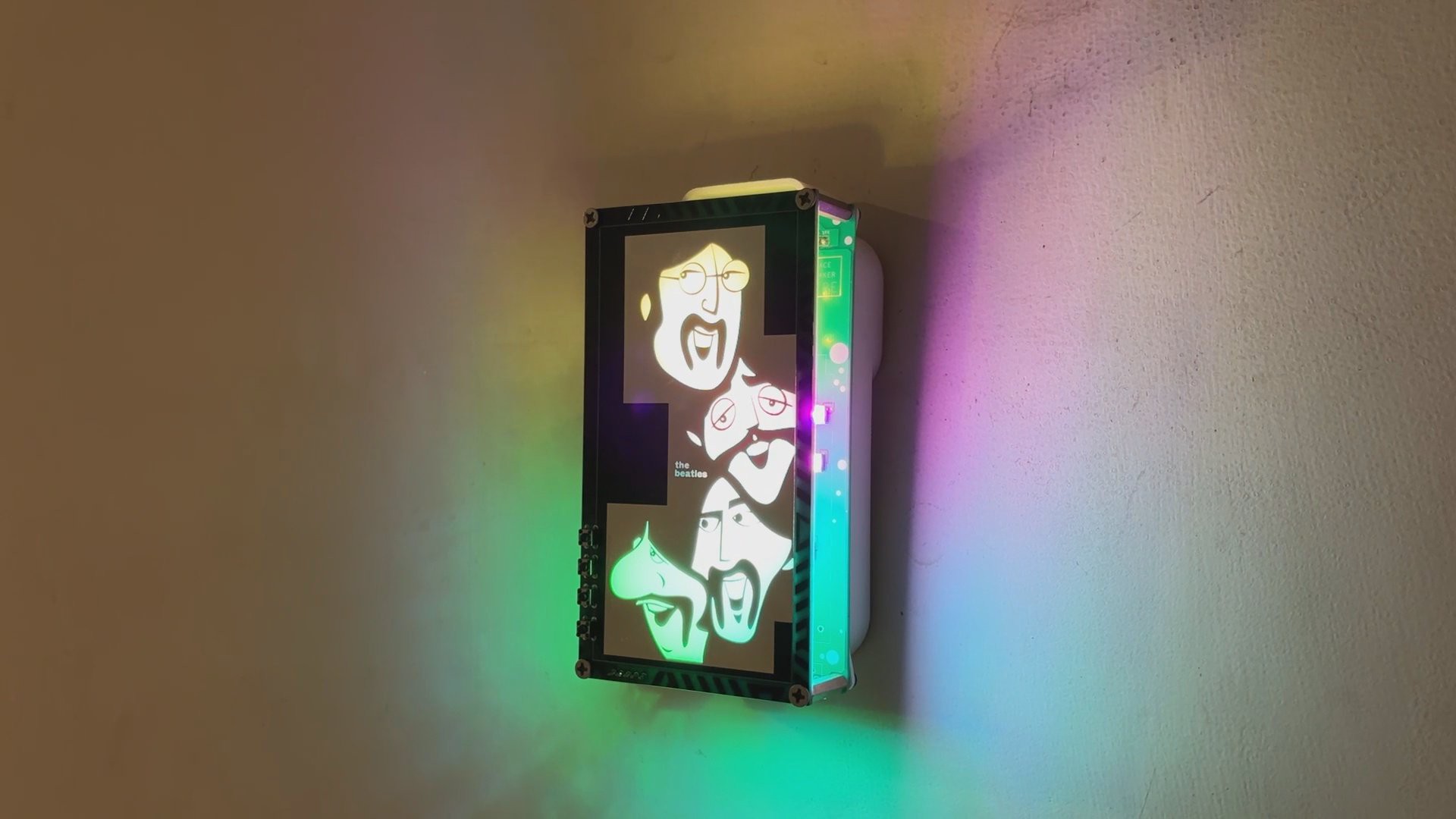
Using my electronics skills, I turned the whole idea into a glowing, music-playing tribute. It’s not just a lamp or just a music player; it’s a fusion of ideas: a custom LED-lit music box, a visual homage, and a piece of electric art.
I’m not even sure what to call this device for now; I’m going with Let It Glow.
Drop your name suggestions in the comments.
Materials Required
These were the materials used in this project:
- Custom PCBs
- Raspberry Pi PICO 2
- WS2812B RGB LEDs
- DF MINI PLAYER
- SD CARD
- IP5306
- 10 uF 1206 Capacitors
- 100 nF 0603 Capacitors
- Type C Port
- SMD Indicator LED 0805 Package
- Push Buttons 4x4
- Li-ion Cell
- 3D-printed parts
- M2.5 Screws
- M2.5 PCB standoffs
PCB ART
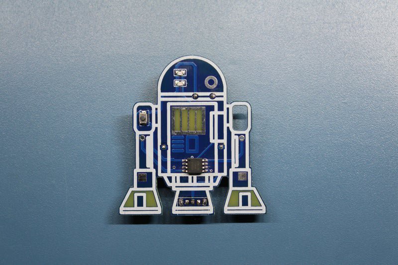
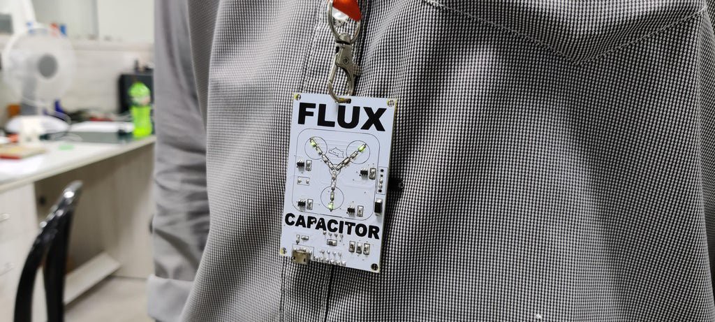

I’ve always loved art, especially painting. So when I started learning electronics, I was instantly intrigued by how makers were turning PCBs into visual canvases. Logos, illustrations, and patterns are all etched into the solder mask and silkscreen layers. That’s when I knew I had to try it myself.
My journey into PCB art began with a Flux Capacitor board, where I used LEDs to recreate the iconic flux capacitor design from Back to the Future. That project gained attention on Hackaday and other maker platforms, and it sparked a whole series of creative builds.
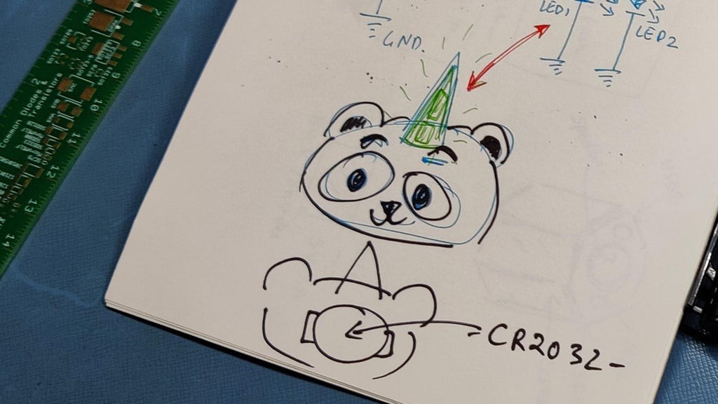
Next came Pandacorn, which was a panda with a unicorn horn. I placed all the SMD components and LEDs on the bottom side of the board and designed the panda illustration on the top. The horn area had the solder mask removed from both layers, allowing light from the flipped LEDs to shine directly through the board. I first saw this clever trick in a Hackaday SAO badge, and it opened up a whole new way of thinking about PCB layering.
Since then, I’ve created multiple themed boards inspired by Halo, Attack on Titan, heart-shaped badge, R2-D2, and more. You can check them all out on my Instructables page.
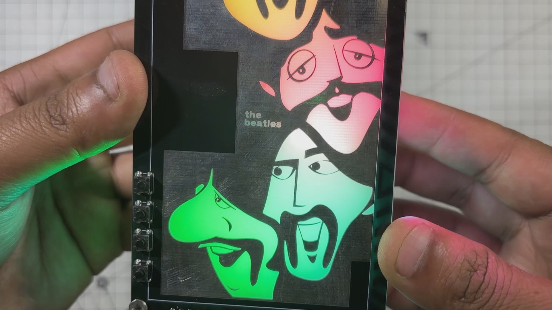
For the Beatles-inspired art board, my approach was simple but intentional. I searched for a cartoon-style design of the original Beatles that I could replicate on a PCB. Then I used solder mask openings on both the top and bottom layers to control how light passes through. RGB LEDs mounted on the lower PCB shine upward, illuminating the artwork from behind. The result is a glowing tribute where electronics and illustration merge into one expressive piece.
This is what PCB art means to me: turning circuits into stories and solder mask into brushstrokes.
DESIGN
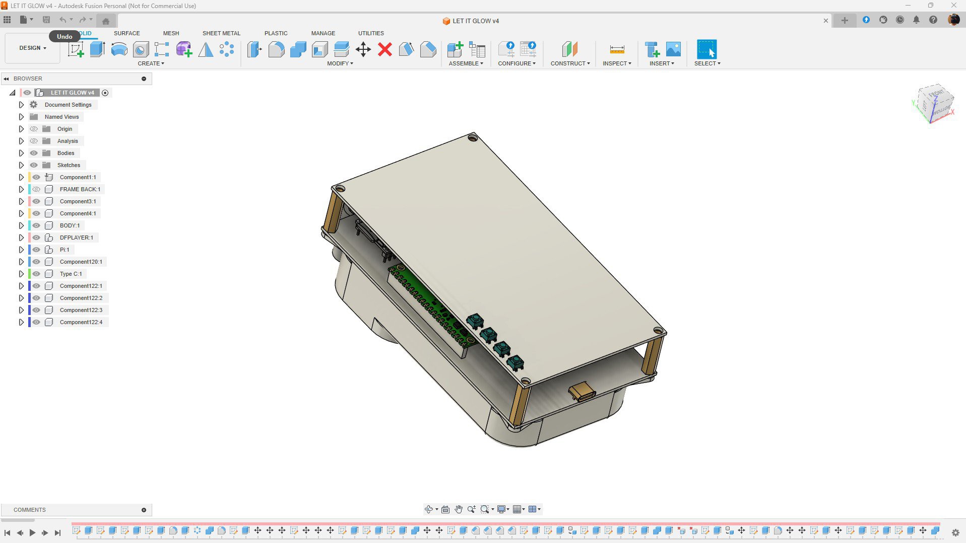

Before starting the PCB design, I first created a 3D model in Fusion 360.
For projects like this, a 3D Model is super crucial, as it allows you to finalize the size and placement of major components, which affects the PCB layout. Precise dimensions and positioning are essential when working with tight tolerances and layered boards.
In this build, the speaker plays a central role. It not only needs to be supported securely within the enclosure but also positioned to enhance sound quality. That’s why designing the enclosure early was key; it helped shape both the mechanical and acoustic aspects of the project.
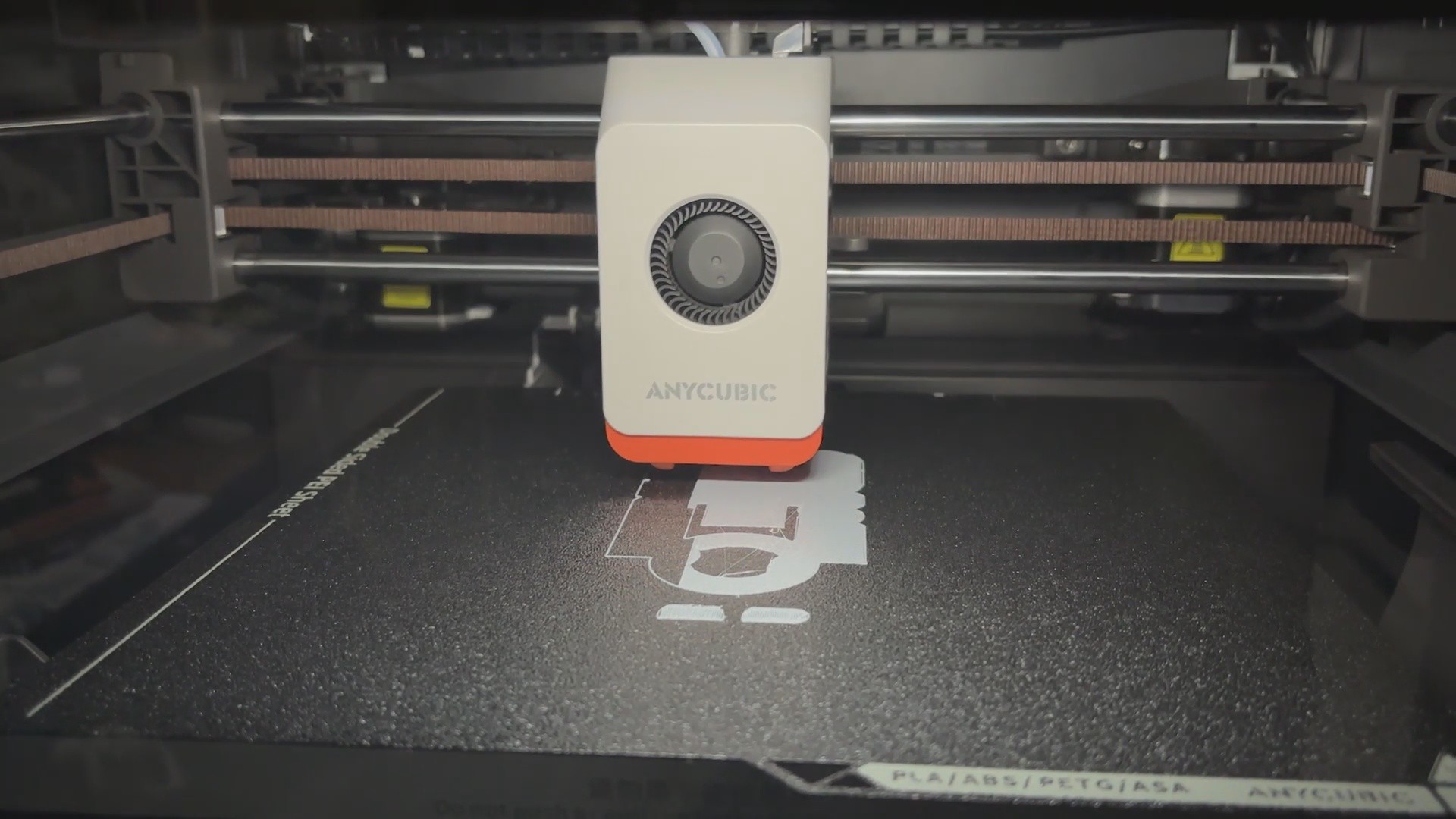
Once the model was complete, I created an enclosure that houses both the speaker and the lithium cell. The mesh file was exported and 3D printed using my new Anycubic Kobra S1 — giving the project a clean, custom-fitted shell that ties the whole build together.
PCB DESIGN
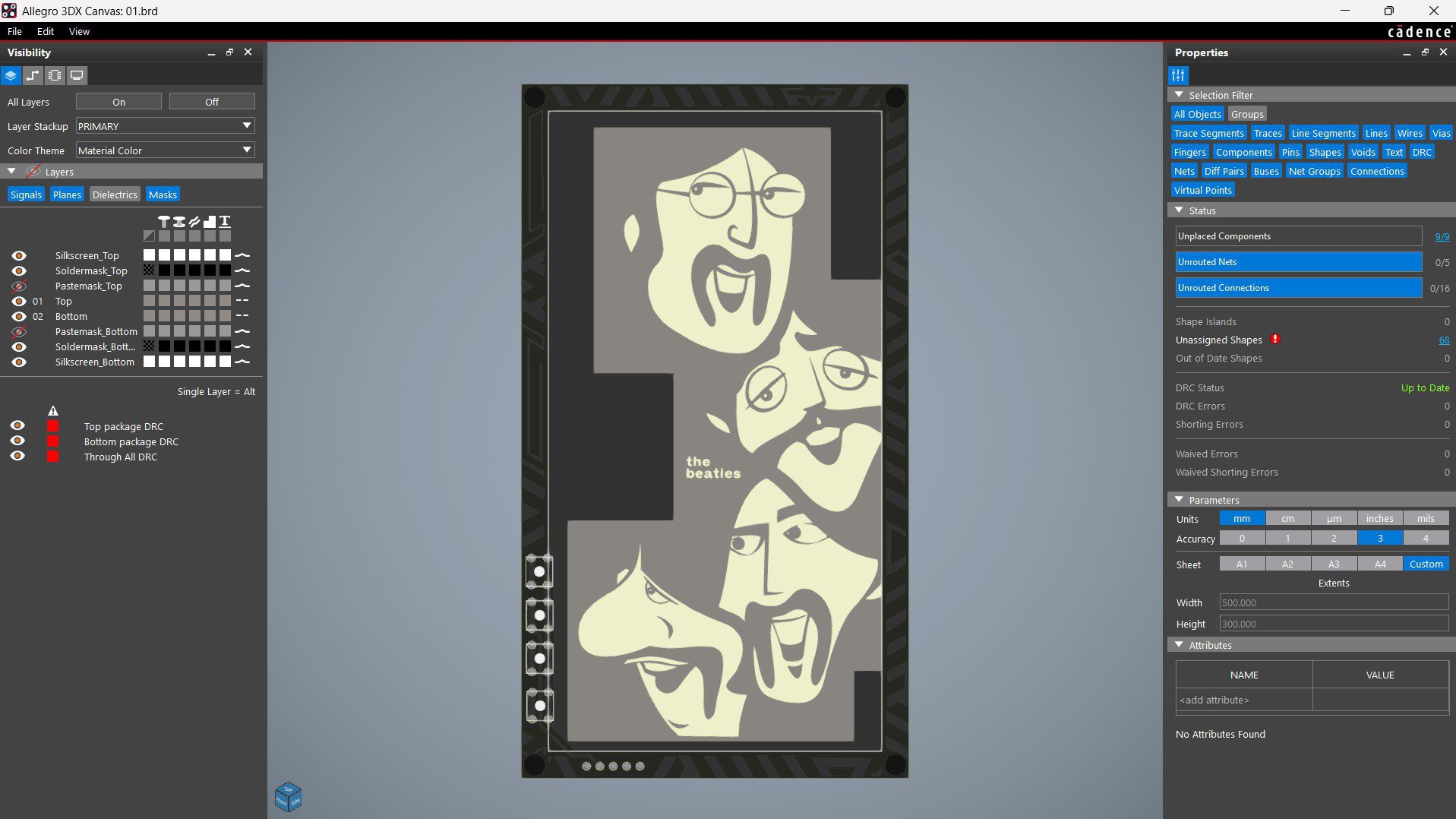

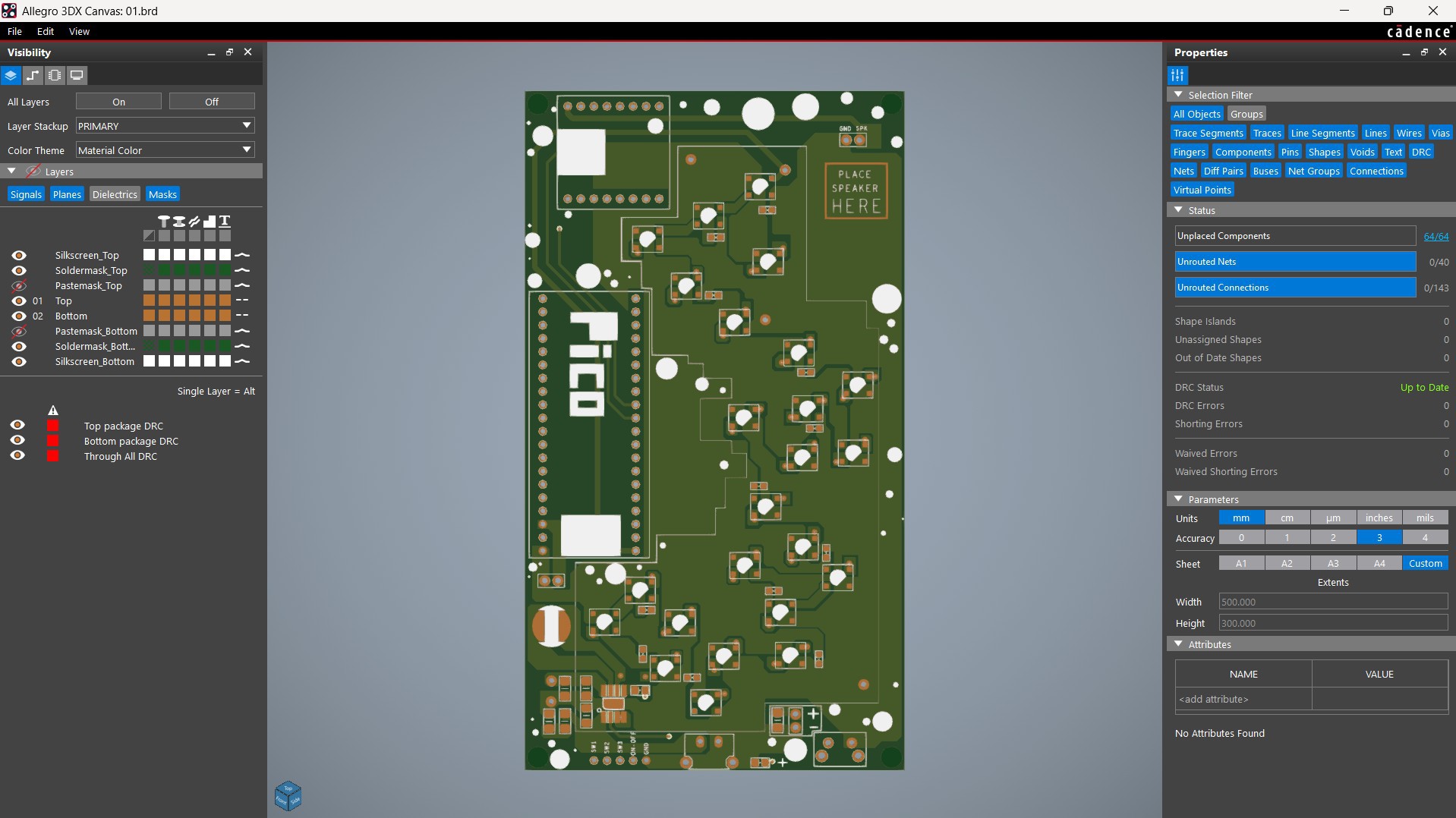


Next comes the most important section of this project, the PCB design process, which involves two separate PCBs: the Front Art Layer and the Main Board that holds all the electronics.
We begin with the Main Board by creating a simple schematic that includes the Raspberry Pi Pico connected to the DFPlayer Mini and a CON5 header pin. This header connects GPIO12, GPIO13, and GPIO15 along with GND from the Pico. These three GPIOs are used as button inputs for next track, volume up, and volume down functions.
The DFPlayer Mini is connected to GPIO7 and GPIO8 of the Pico, which serve as its TX and RX pins.
For the lighting effect, we use 24 WS2812B RGB LEDs connected in series to form a continuous chain. The DIN of the first LED is connected to GPIO0 of the Pico, with VCC connected to 5V and GND to ground. Each LED has its own decoupling capacitor placed as close as possible between its VCC and GND pins.
For power, we’ve included our trusted IP5306 — a power management IC we’ve used in many previous projects. It provides a stable 5V output from a 3.7V lithium cell and includes features like charging indication, low battery warning, and high/low voltage cutoffs, all essential for safe lithium cell operation.
For the Front Art Layer, we took the image found on Pinterest, scaled it to match the PCB dimensions defined in the 3D model, and converted it from JPG to a monochrome BMP format. This allowed us to import it into the PCB CAD tool as a logo.
We applied copper etching to all black areas in the image, while the white regions were left as solder mask openings. The same solder mask openings were added to the bottom layer as well. The idea was to use the etched areas to block light and the solder mask openings to let the RGB glow pass through.
After finalizing both designs, we exported the Gerber files and sent them for PCB manufacturing.
NextPCB PCB Service
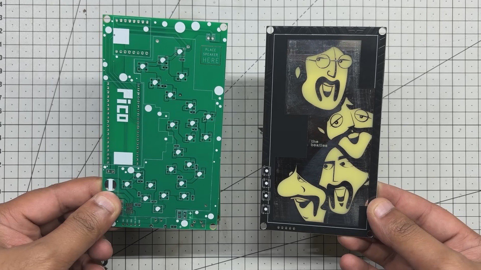
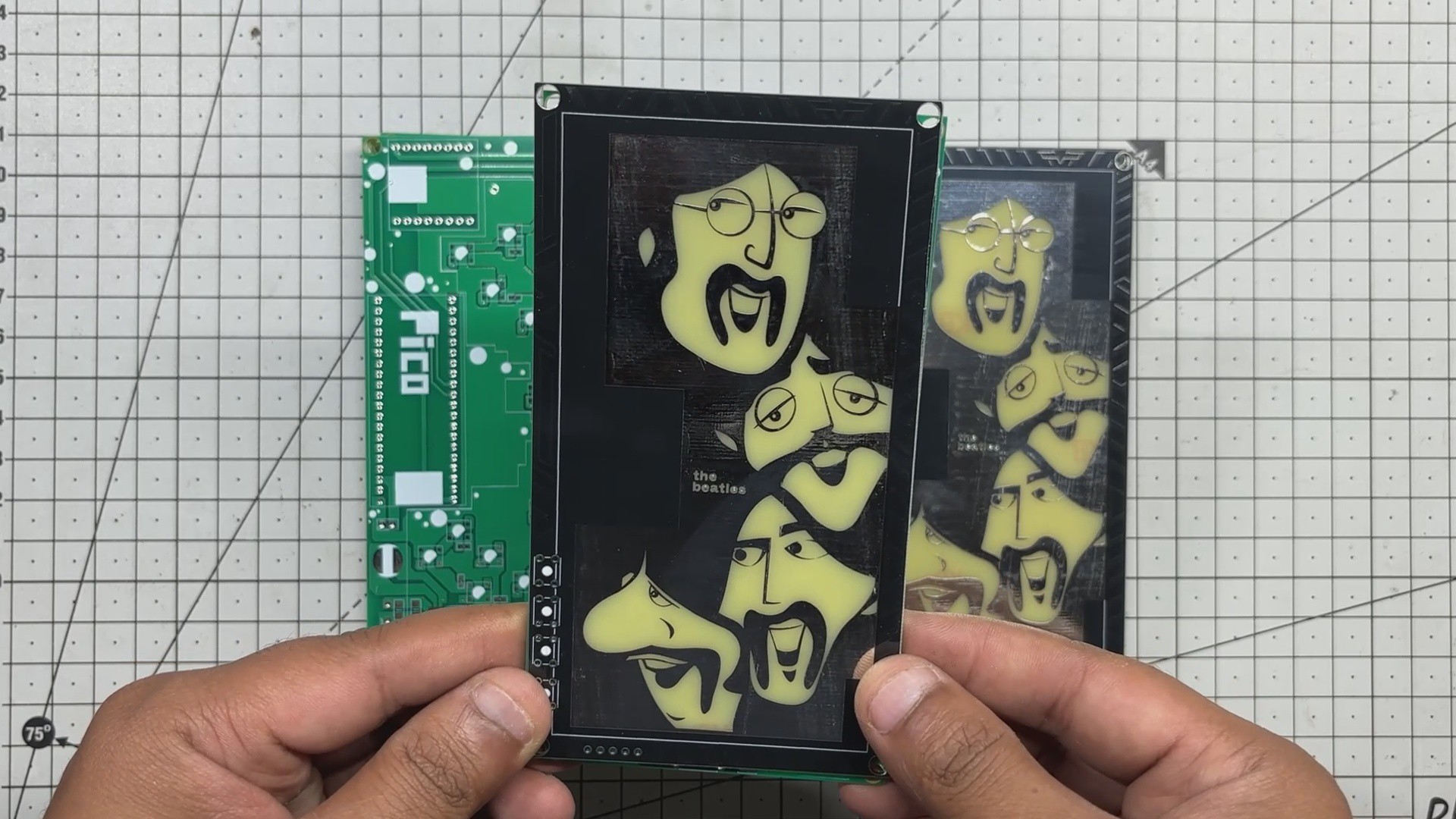
After completing the PCB Design, Gerber Data was sent to HQ NextPCB, and two orders were placed, one for a Black soldermask and other for Green solder mask with White silkscreen.
After placing the order, the PCBs were received within a week, and the PCB quality was pretty great.
In addition, I have to bring in HQDFM to you, which helped me a lot through many projects. Huaqiu’s in-house engineers developed the free Design for Manufacturing software, HQDFM, revolutionizing how PCB designers visualize and verify their designs.
Take advantage of NextPCB's Accelerator campaign and get 2 free assembled RP2040-based PCBs for your innovative projects.
https://www.nextpcb.com/blog/rp2040-free-pcba-prototypes-nextpcb-accelerator
This offer covers all costs, including logistics, making it easier and more affordable to bring your ideas to life. SMT services can be expensive, but NextPCB is here to help you overcome that hurdle. Simply share your relevant project, and they'll take care of the rest. Don't miss out on this amazing opportunity to advance your tech creations!
HQDFM: Free Online Gerber Viewer and DFM Analysis Tool

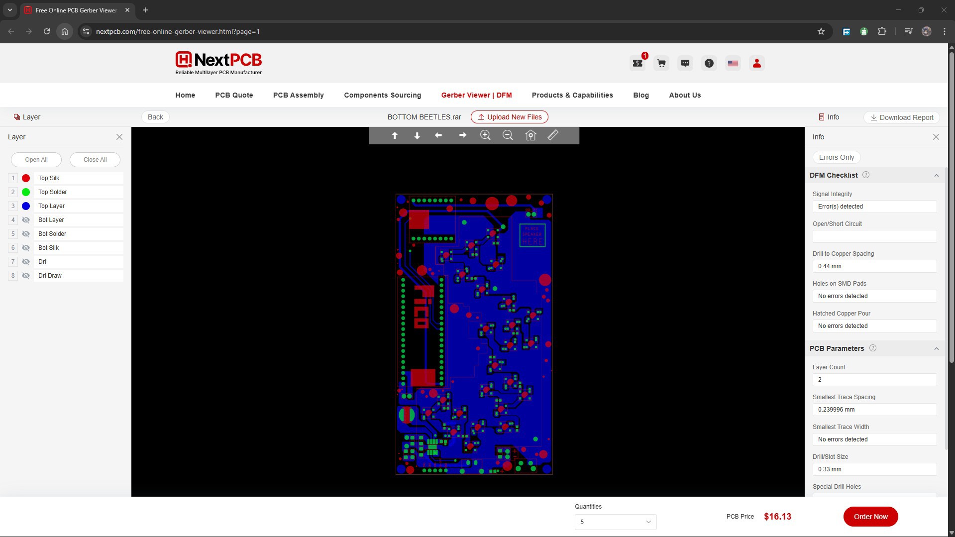
Also, NextPCB has its own Gerber Viewer and DFM analysis software.
Your designs are improved by their HQDFM software (DFM) services. Since I find it annoying to have to wait around for DFM reports from manufacturers, HQDFM is the most efficient method for performing a pre-event self-check.
This is what I see in the online Gerber Viewer. It's decent for a quick look but not entirely clear. For full functionality—like detailed DFM analysis for PCBA—you’ll need to download the desktop software. The web version only offers a basic DFM report.
With comprehensive Design for Manufacture (DFM) analysis features, HQDFM is a free, sophisticated online PCB Gerber file viewer.
With over 15 years of industry experience, it offers valuable insights into advanced manufacturing processes. If you’re looking for reliable PCB services at a budget-friendly price, HQ NextPCB is definitely worth checking out.