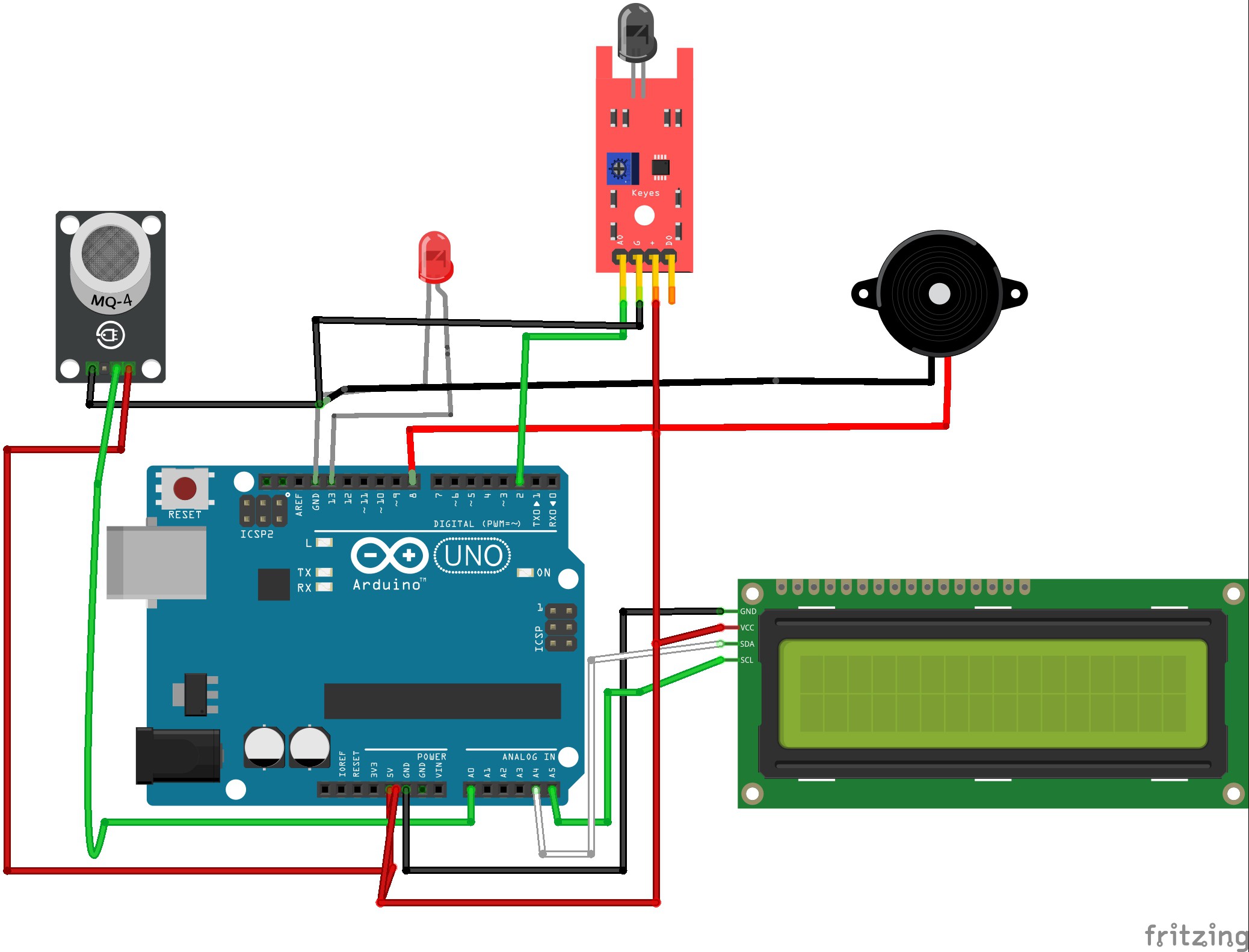
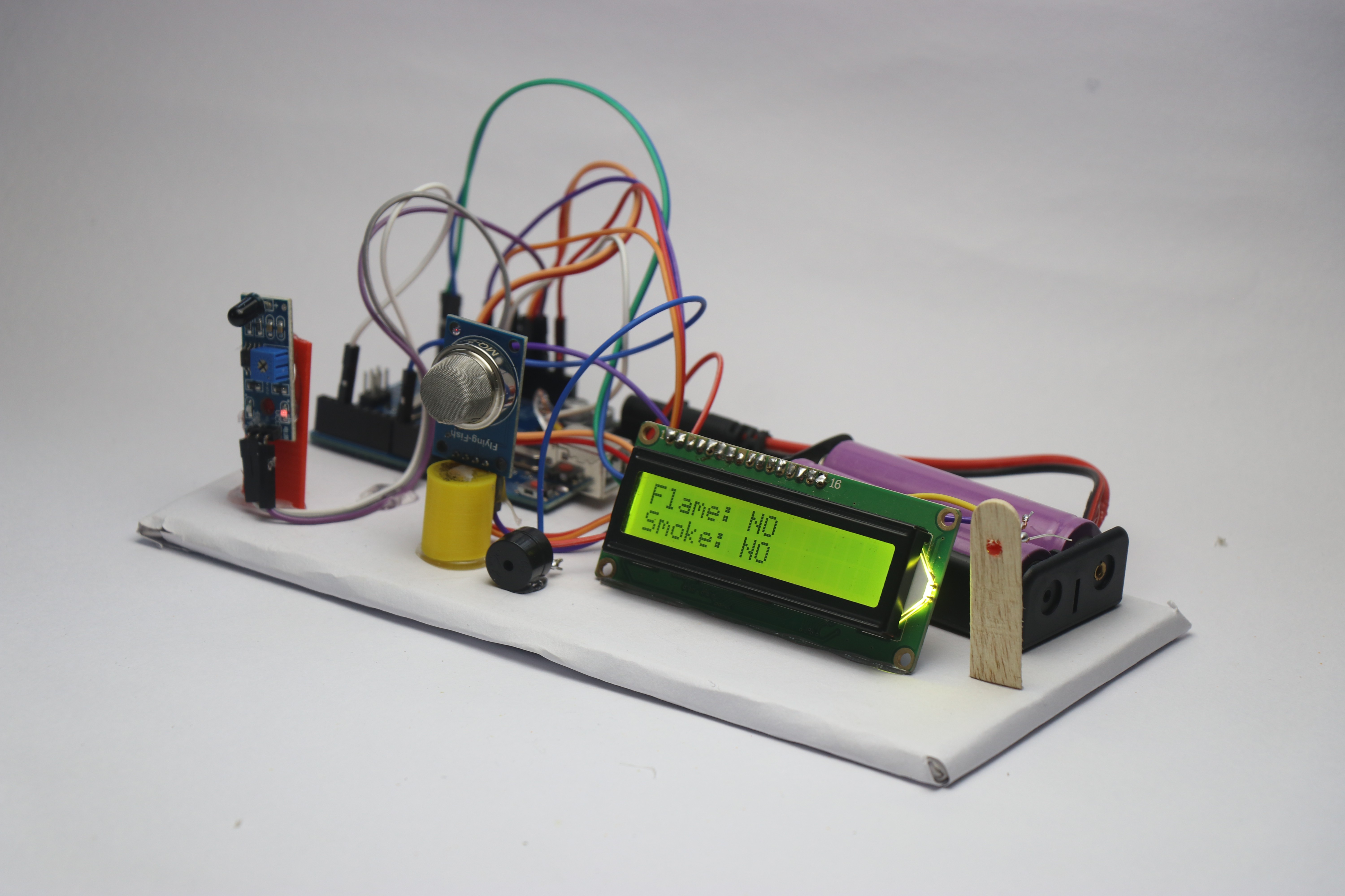
• 1
    Circuit Building

    The circuit is simple and dont panic by seeing the cable connections! I will make the circuit simple by breaking down the steps one by one component wise.

    To begin with there are 5 components and i will go with connections of every one

    Flame sensor

    This has 3 pins and the signal pin is connected to D2

    Whereas the power and ground is connected to 3v and GND pins respectively

    Gas sensor

    Here also the Ground and Power pins are connected to GND and 5v Pins of the Uno board

    The signal pin that is A0 on the gas sensor is connected to A0 on the Uno board

    Buzzer and LED

    Sinec we have limittaion of the GND pins of the Uno board i have connected the ground of both componnets into one

    Whereas the positive pins from LED is connected to D13 and the Buzzer is connected to D8

    LCD module

    Scl and Sda is connected to A5 and A4 pins whereas the Positive and Gnd is connected to 5v and the ground pins respectively.

    This completes the connection, Now open your IDE and use the below file for program, You may need to install drivers if it shows errors.

    Select proper port and board type and click on upload button and now we can move ahead with next steps.

    You can take your hobby projects to next level by upgrading the parts with CNC parts from JLCCNC.

    Can you believe they are offering CNC Machining at just $1? Claim the $70 welcome coupons from JLCCNC Here

    They use advanced technology to produce CNC parts that can suit your various needs, So for your next project keep JLCCNC in your mind.

  • 2
    Setting Up Components

    I will use a rectangular piece of cardboard to place all the components, Well the size of cardboard is left to you.

    Since i wanted to make this project look compact i used a small piece of cardboard, If the size is bigger you may have to extend the length of cables.

    Start by placing the arduino uno board first on the cardboard and secure with double side tape or glue(slighly small amount).

    Later i will place the LCD and to secure the base i used small amount of hot glue.

    I had some 3d printed parts that i upcycled from my previous project to hold the gas sensor and the flame sensor.

    The led was carefully connected to popsicle stick holder that gives a great look.

    Secure all these components well and make sure you have some space reserved for the battery also(i kept it on the back side of the LCD).

    Finally after all this is complete, connect the dc pin to the uno and now we are ready with this project! Cant wait to test this and let see how this is done in the next step

  • 3
    How to Use

    I will use battery supply to power this project, I used 2 lithium ion batteries connected to holder and then to a DC pin.

    This is then connected directly to the uno board power supply, After you connect this to uno you should see the message on LCD screen and all the components will be active.

    Allow few seconds for the gas sensor to work efficiently since it has a gas sensing filament cased inside mesh that will be ready to use after heating.

    Now you can test the project, I used lighter for flame and when you bring it near to the flame sensor the red led glows along with buzzer and the LCD shows flame detected as Yes.

    Now i only passed some gas from the same lighter to the gas sensor and like the previous one here also you can see the alert system getting active.

    Also did you know not only one but you can expose both flame and gas sensor together and see the device working properly.

    Untill the sensor stops sensing the gas or flame the buzzer will beep, You can take this project one step further by connecting water spray pump also instead of LED.