 JP Gleyzes
I wanted a wireless buddy box for my Radiomaster TX16s
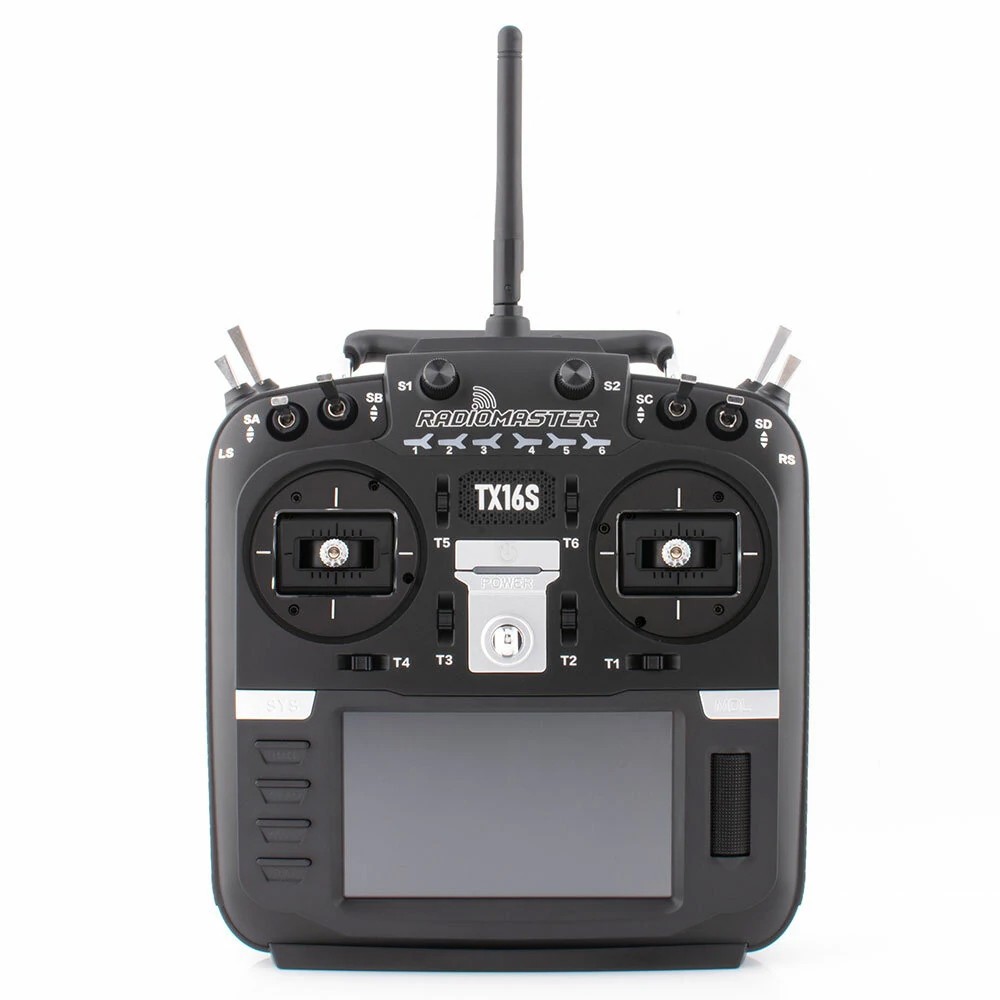
This buddy box would allow to wireless link two TX16s in Master/Trainer mode.
Radiomaster is already selling this kind of module.
However their modules need to be linked (soldered with) mini receiver to work. Furthermore they are "one way" modules (trainer to slave) and finally quite expensive...
So decided to build mine with the following specifications:
- cheap (two fully working modules for less than 20$)
- auto configuration as master or slave or vice versa
- auto binding between two modules
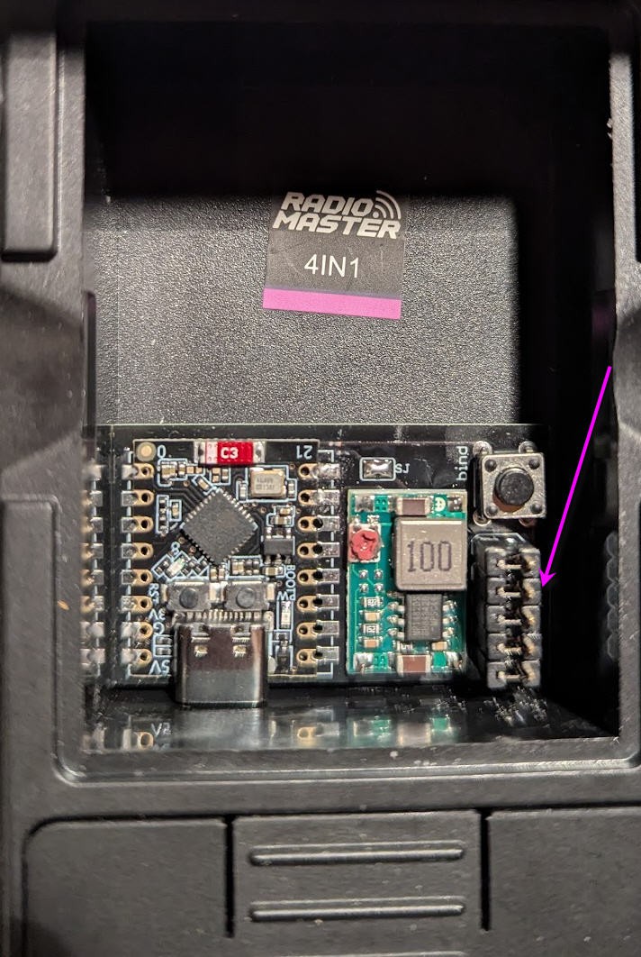
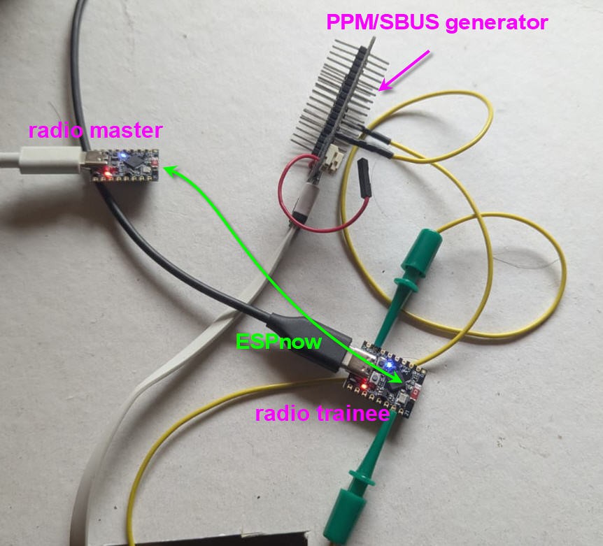
- fully hidden into the "external module" compartment (no dangling wire outside the radio))
- no modification into the TX16s
- no firmware modification of your TX16s (stock EdgeTx firmware)
- high speed wireless communication with about 20m range
- automatic On/Off of the buddy boxes via EdgeTx
- compatible 16 channels SBUS and PPM signals
- extensible to further options (teasing: a bluetooth low energy joystick and more to come !)
Before going further here is the final result in video
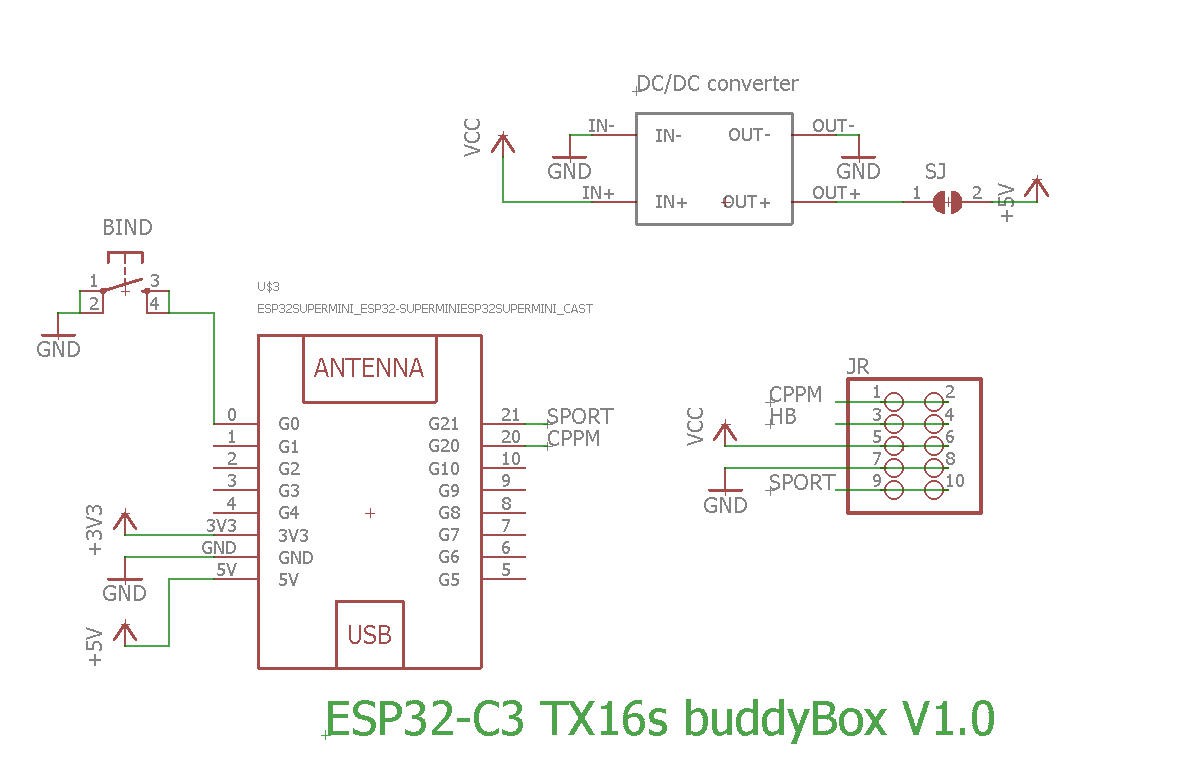
Schematics
Schematics couldn't be more simple !
Version V1.0 is powering the ESP32 via the 5V pin
V1.1 is powering the ESP32 via the 3.3V pin. Apart this, both boards are strictly identical.
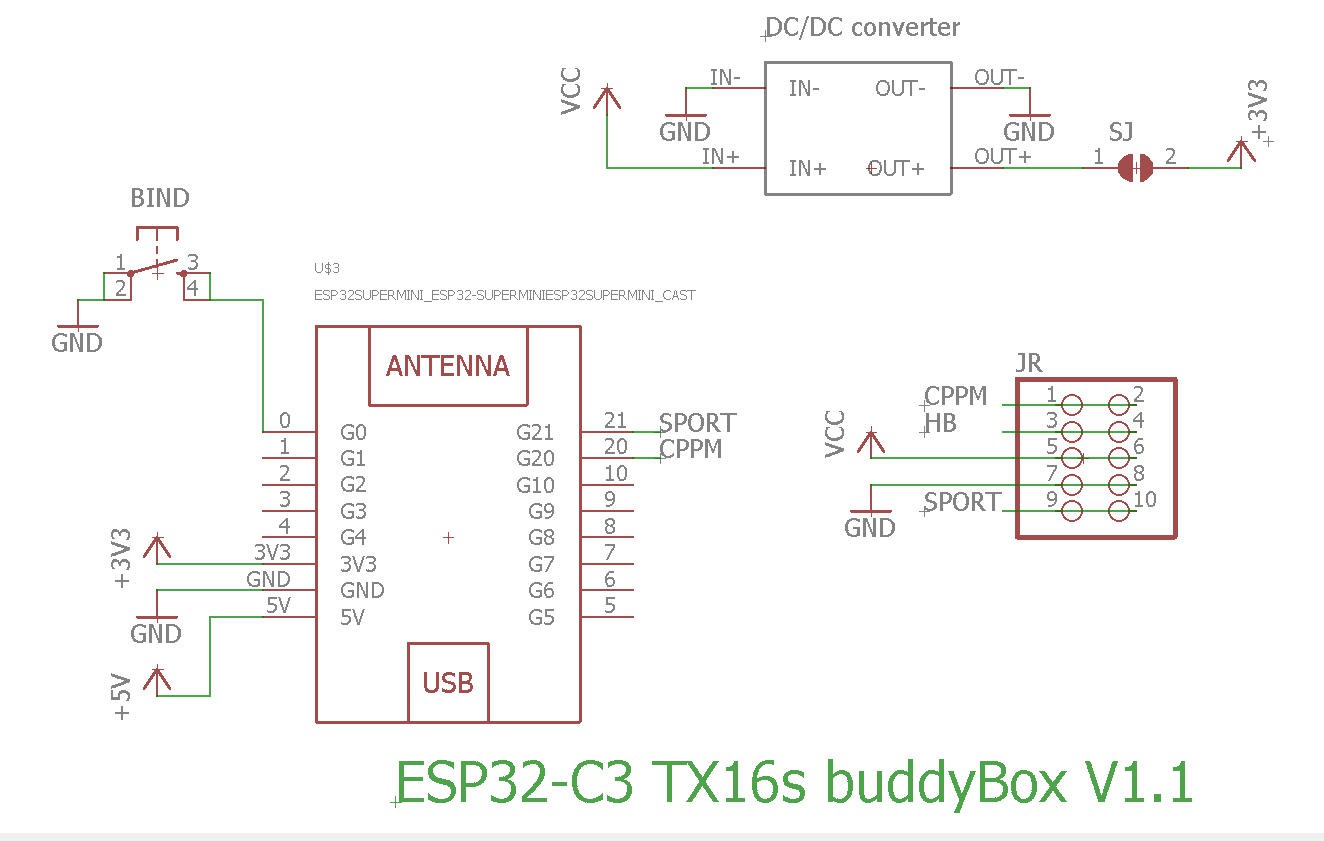
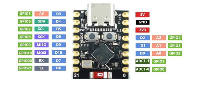
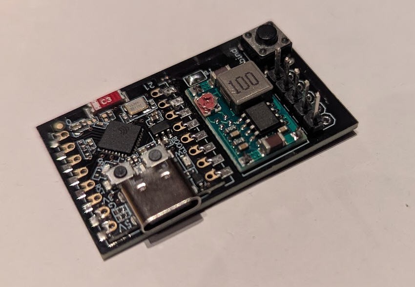
Basically, almost nothing but an ESP32-C3 Super mini
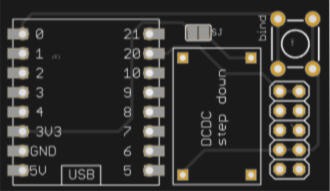
PCB
PCB is also simple and must be small enough to be hidden into the "external module" compartment of the radio
The PCB was kindly sponsored by PCBWay and is as usual of excellent quality.

You can order it here : PCBWay shared project. It's cheap, delivered very fast and so professional looking!
and if you are new to PCBWay please use this affiliated link : https://pcbway.com/g/o35z4O
soldering the board is very simple.
When finished it can be placed into t the external bay of the radio and connected with 5 "jumpers" glued together
Power
As said above, to power the ESP32-C3 "supermini" MCU we need either 5V or 3.3V.
- Powering with the 5V pin will turn on the red led of the ESP32-C3 while switching also on a linear 3.3V voltage regulator into the board
- Powering with the 3.3V will NOT turn on the red led of the ESP32-C3 and will bypass the internal linear 3.3V voltage regulator
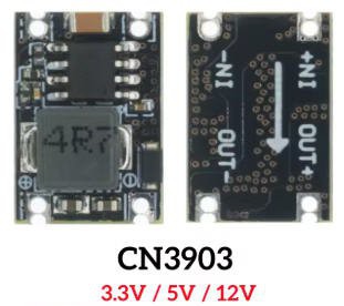
- V1.0 of my board uses the first option. You will thus need a 5V DCDC step down
- V1.1 of my board uses the second option. You will thus need a 3.3V DCDC step down
If you use an adjustable DCDC converter as below:
You will have first to tune the trim pot value in order to get 3.3V or 5V output (do not power anything else before...) when this is achieved, you can paint the trim pot with a drop of nail varnish to fix the potentiometer then (and only then) solder the SJ solder pad on the top side of the PCB. The 3.3V or 5V will now flow to the ESP32
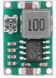
if you use a fixed output DCDC stepdown converter as below:
You will have to order the right one (either 5V for V1.0 board or 3.3V for newer V1.1 board)
I strongly advice that you measure output voltage before soldering the SJ solder pad on the board !
Finally which solution is the best V1.0 or V1.1 ?
The V1.1 version is slightly better as the internal linear voltage regulator which drops down 5V to 3.3V, into the ESP32 Super mini, will be bypassed; leading to less power consumption into the battery of your radio.
Indeed DCDC step down converters have a much better efficiency than linear regulators.
Although the gain could be considered as "marginal", the V1.1 board is now the default solution if you order the PCB on PCBway site.
I must say that It's not worth buying the new V1.1 for those (like myself !) who already have a V1.0 board
How does it work ?
To understand how my module works we must first have a look at the JR connector into the external module bay on the back side of the radio.
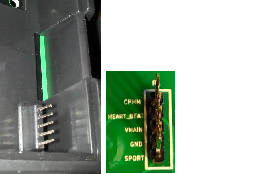
two pins are very interresting :
- CPMM
- SPORT
while two more seems to be self explainatory (but are not !)
- VMAIN
- GND
Let's start by these ones.... Gnd is indeed Ground. But VMAIN is not a "nice" voltage for micro controllers... It's indeed the voltage of the battery of your radio. Classically it's a 2s Li-Ion (or lipo) pack with a fully charged voltage around 8.4V... Too much for an ESP32-C3 which needs 3.3V
So I will pick up this voltage but use the DC/DC step down converter to reduce it ...
Let's now have a look at CPMM and SPORT pins
CPMM
I have found that CPMM pin can output either PPM signal or SBUS signal.
Be aware that CPMM pin on the TX16s outputs 5V logic signals.
This is not an issue for ESP32 chips as they are tolerant to input 5V signals on digital inputs only
PPM signal output:
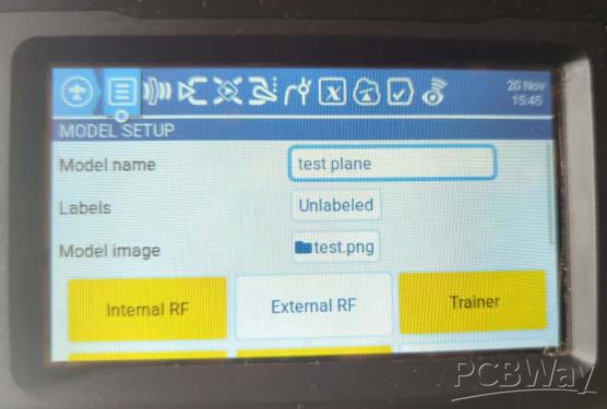
You will have to power the external module of your radio and set it to "PPM". This is done via the "model Settings" menu
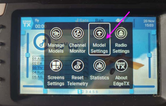
then select "External RF" option and be sure that "Trainer" is set to off (not yellow !)
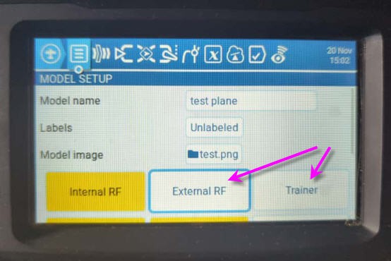
Now choose the "PPM" option and exit
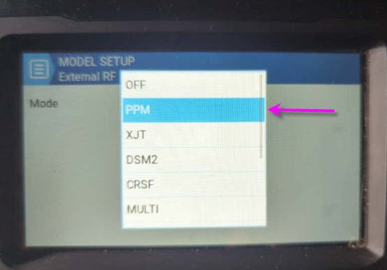
Your radio will now output PPM signal. Increase the channel numbers to 16 and you are good to go : the 16 channels of your slave radio will be output on the CPMM pin

And your "external RF" module is now painted in yellow !

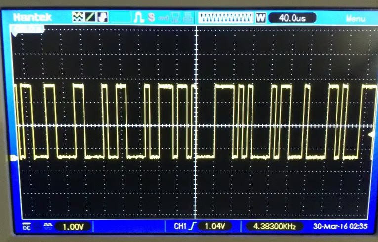
The PPM signal should look like this (Rx line : but with 16 channels instead of 7 or this scope)

PPM signal is however an "old fashion" way to transmit RC signals. My board can automatically detect and read this signal which could be usefull if your slave radio is quite old and do not have a better interface !
But in our TX16s we do have SBUS interface !
SBUS signal output
Using the same principle as above we can select SBUS into our "ExternalRF" menu

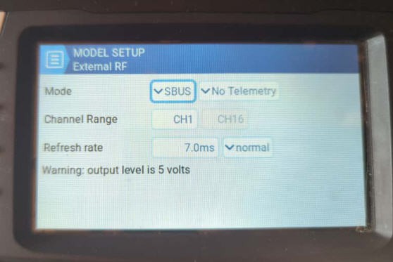
And we are good to go, CPMM pin will now output SBUS signal.
Sbus is a pure serial protocol much faster than PPM and without "jitter" issues, so much more precise than PPM.
So my module will also automatically detect and decode SBUS. I do strongly recommend to use Sbus for your settings if you set up trainer/master between two SBUS compatible radios (such as two TX16s)
SPORT pin
The S port (Serial Port) pin will be used to input SBUS signal into our "Master" TX16s radio
To do this you have to go again into the model Setting of your plane and be sure that the "externalRF" module is Off before selecting the "Trainer" menu
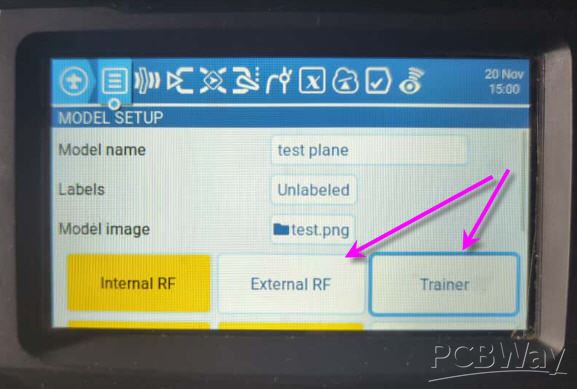
into the "Trainer" menu simply select "Master/SBUS Module"
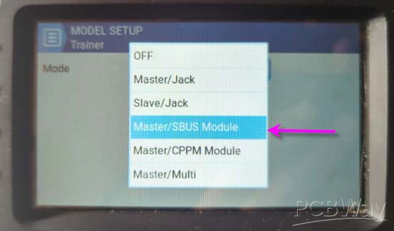
Your trainer signal will now be sent to the Master radio via the Sport pin
You can check that the "Trainer" button is now "yellow" while the "ExternalRF" is off
Now you still have to configure your radio to enable training. This is done at the "radio" level
two steps are needed:
1) create a global function enabling the trainer mode when a button is pressed (or swithed). Here SJ button
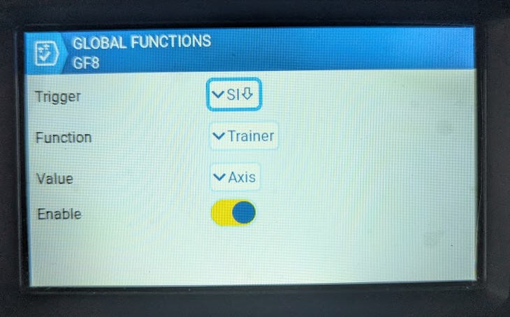
When pressing SJ button (the one behind your radio), it activates trainer mode and consider that channels are "Axis" at the input level of EdgeTx
2) affect the axis to the right channel
This is done when pressing the "two people button" at the radio level
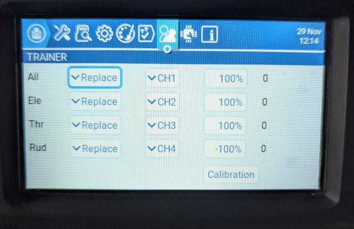
You can then reaffect the trainer axis to the master radio input channels. And do more complex options (adding master and slave, replacing, avoiding a certain channel and even calibrating the slave ...)
My simple setup is to create a "dummy" plane on the slave radio to center each axis without any trim nor mixer and it's ok like this !
Your radio will thus output the channels to your plane using the "Internal RF" module, while getting the trainers ones from the SPORT pin and mixing them with the Master ones via the classical way.
Summary
In a nutshell the configuration for your TX16s radios should follow these simple guidelines
Trainee radio
- "Trainer" button OFF
- "ExternalRF" button On and configured to output SBUS on CPMM pin
Master radio
- "Trainer" button ON and configured to input SBUS signal on Sport PIN
- "ExternalRF" OFF
- "internal RF" active to control your plane via the on board receiver
Binding the Trainer and Master buddy boxes
After previous chapters we know how to configure your radios as Trainer or Slave, but we don't know yet how to let the budy boxes speak to each other !
We need to "bind" the buddy boxes.
Communication between the two boards will use the Espressif proprietary "ESPNow" proptocol".
ESPNow is a fast reliable and efficient way to transmit "payload" over wifi.
The payload packet must be less than 250 bytes. As we do have 16 channels to transmit, it's more than enough !
- Binding will be automatically done by the firmware while pushing the "bind" buttons of the boards during boot when powereing the board.
- Once done, binding will be permamently stored into the ESP32 EEPROM (unless you decide to "bind" again with the button).
- Binding will allow a two ways communication. So it must not be re done if you decide to swipe the Master and and the trainer radios ! (you will jut have to configure them as shown above).
Remember that the buddy boxes will be powered (when the radio powers on) when "external RF" or "Trainer" are not "OFF".
This also means that if ExternalRF and Trainer are both set to OFF, the buddy box will not be powered (handy trick !)
Software
Software is limited to the ESP32-C3 firmware. Same firmware will be used on Master or Trainer buddy boxes !
You can find it on my github page : https://github.com/f2knpw/Radiomaster_TX16s_buddy_box
Firmware has been heavily tested while PCB was in production. Here is the resul of these tests :
- ESPnow auto binding succesfully tested
- auto detection of PMM or SBUS signals successfully tested
- auto configuration as master or student successfully tested
- 16 channels sent and received at more than 300 Hz
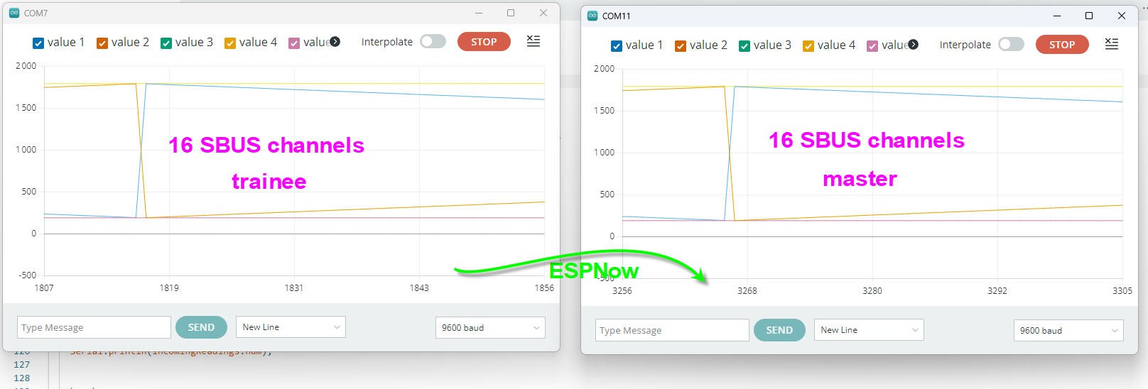
On the following picture an ESP32 is acting as a PPM or SBUS generator, it sends the signal as CPMM pin would do to the trainee module. Signal is sent to the master module via ESPNow
Real time between both modules is sustained (even with debug traces active !)
This code relies mostly on three very cool libraries:
- ESPNow from Espressif for communication between master and student
- Sbus Library for decoding/coding Sbus signals: https://github.com/bolderflight/sbus/tree/main
- ESP32ppm library for decoding PPM signals: https://registry.platformio.org/libraries/fanfanlatulipe26/ESP32_ppm
All these libraries are "clever ones" as they do exploit hardware peripherals into the ESP32-C3 chip. So they induce a very low latency into the software which can run a complete loop at more than 300Hz
If you are new to ESP32 stuff, then to compile your code follow this log.
Next step will be radio to radio test !
Testing protocol
test 1 : slave (simulated radio) + slave buddy box to Master buddy box in TX16s
In this video you will see two buddy box boards used to communicate in slave/master mode
- the slave uses a simulated SBUS signal entered into thte buddy box
- slave sends 16 channels to master
- master buddy box board is installed into the TXs16 radio
- on/off of the master buddy box is demonstrated
test 2 : slave (TH9x PPM radio) + slave buddy box to Master buddy box in TX16s
In this video you will see two buddy box boards used to communicate in slave/master mode
- the slave uses an old TH9x radio with PPM signal
- slave sends 8 channels to master
- master buddy box board is installed into the TXs16 radio
- auto config from SBUS to PPM of the slave buddy box is demonstrated
- loss/retrieve of slave signal is demonstrated on the master
test 3 : slave TX16s + slave buddy box to Master buddy box sending SBUS to TX16s radio
In this video you will see two buddy box boards used to communicate in slave/master mode
And here is the result
test 4 : in flight
All the previous tests were done at home, so might be not realistic compared to "on the field" flying test !
Yesterday, just after christmass, we flew an easyglider in student/master mode.
- My very old TH9x was equiped with one module as shown in test2 above. It was the "student"
- My TX16s, with another one and was the "master"
We flew a full battery, that is around 30 minutes trying evrything possible including take off and landing.
The student was a very good pilot. He told me that the behavior of the plane was totally normal with no jitter nor lag nor latency into the sticks.
The buddy box is thus fully functionnal !
To test the range between student and master we even performed a "back to back" test. student and master holding their radio on their belly. This is a configuration where Wifi signal had to cross two human bodies... In this particular configuration we got "loss of trainer signal" followed by "trainer signal recovered" messages.
So we can confirm that in "normal usage" where student and master are positionned close everything is fine. But range will not exceeed 10 to 20m which is what I expected !
Add a bluetooth Low Energy Joystick in your radio
As I said at the very beginning, this buddy box is "open" and as such allows several "improvments".
Here is one of them : Your Tx16s (or any other PPM or SBUS radio) can be seen as a Bluetooth Low Energy gamepad !
Joystick is seen in Windows with the name "Radiomaster TX16s"

and after pairing (no password) it will be visible as a standard gamepad
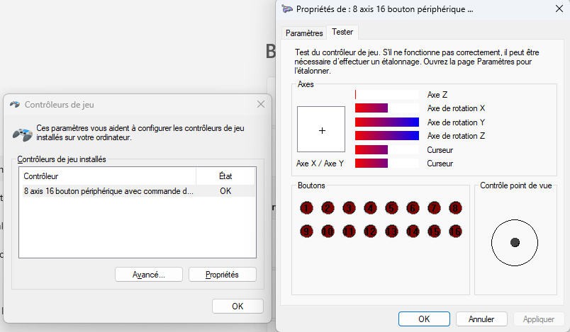
All modern flight simulators will see it and will allow to remap the 8 available channels
You can of course assign the channels into the mixer of your radio as well
Tested with Multiplex "MultiFlight", Reflex XTR2, SeligSIM 2024.5
Phoenix RC is the only one which does not recognize the joystick, willing of a wired USB one...
As an example here are the axis assignments under Reflex XTR2

joystick axis are set in the order (x, y, z, rx, ry, rz, slider1, slider2) respectively for ch1 to ch8 of the SBUS/PPM message
By default joystick is available when the buddy box is in "student mode" (ie receiving PPM or SBUS) You can desactivate the joystick when commenting this line of code :
#define HAS_JOYSTICK
Pilot a plane with a joystick
With almost the same setup (at least exactly the same onyour master radio) you can pilot a plane with a joystick.
Follow this log for more details.