 Jeroen Brinkman
Intro
This project, the Turing Machine Demonstrator, is a fully realized electromechanical interpretation of the theoretical computing model conceived by Alan Turing in his seminal 1936 paper On Computable Numbers. It transforms the abstract principles of computer science into a physical, functional machine, offering a vivid demonstration of how computation fundamentally works.
This model is widely used to distinguish a calculator from a computer. A system or machine is considered Turing complete if it can, in principle, compute everything that a Universal Turing Machine (UTM) can compute.
The crux
The most challenging part of a mechanical Turing machine is - without any doubt - the Turing tape. A good tape must meet the following four requirements. First, the tape must have at least three symbols: two for processing and one symbol to distinguish a data string from an empty tape, for which the symbols 0, 1, and 'space' are obvious choices. Second, these symbols must be writable onto the tape both manually and by the Turing machine itself, as manual input is necessary to provide the machine with an initial string. Third, it is important that the symbols are clearly readable for both humans and the machine. Fourth, it is desirable that the symbols are obvious rather than encoded, so preferably no colored LEDs or a pawl with three positions.
The Turing tape I designed meets all these requirements. The elegant solution I found, was the trigger that made me decide to build this machine.
The parts
The moving Turing tape
An aluminium profile carries 19 7-segment digits. Each digit can represent a 0, a space, or a 1, and is written using an ON-OFF-ON switch. The tape is moved by a stepper motor and a linear rod. A guidance nut is attached to the profile and moves along the rotating rod. The profile is kept aligned by eight guidance wheels. A positioning LED ensures that the tape is precisely positioned before writing a new symbol.
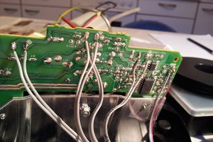
The read head
The tape is read using LDRs. The positioning LED, as well both right segments of the 7-segment display (the “1”) and the left two segments (forming part of the “0”), are detected. When the positioning LED is seen, the tape is correctly placed.
-
If the 7-segment LEDs are off, the symbol is a space.
-
If only the right LDR detects light from both the right segments, the symbol is 1.
-
If both - the left and right segments - LDRs detect light, the symbol is 0.
Special attention has been given to calibrating the light levels. It is important to reliably determine the threshold values that distinguish between LED segments being on or off. This is dynamically handled by the software.
The write head
Two opposing linear actuators are used to toggle the switch and write a symbol on the tape. The actuator retracts when the read head confirms that the required symbol has been correctly written.
The program
The “program” of a Turing machine consists of a state table. For each combination of state and read symbol, the table specifies:
-
The new symbol to write (0, space, or 1)
-
Whether the head must move left, right, or stay in place
-
The new state
To explain how a Turing machine program works, I developed a Turing Machine Game, which allows the player to experience the mechanics of a Turing machine and become a “busy beaver.” See details here: https://hackaday.io/project/203270-the-turing-machine-game
The machine starts with three pre-programmed programs. Depending on the first digit read — 0, space, or 1 — one of these programs is executed.
In the downloadable files you will find a helpful Excel sheet, The Turing Test, which simulates a Turing machine and checks your program quickly and easily.
Entering a program
A program can be entered into the Turing machine using a program reader — the modern equivalent of a punch card. Instead of holes, the program sheet contains a checkerboard-like pattern where...
Read more »


 snowfox
 James Hutchby - MadLab
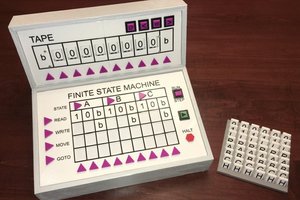
 Michael Gardi
I love this and will be using it as inspiration for my own build!!! Thank you so much for sharing! I am a HUGE Turing fan / geek. I did notice that the Carbide Create files are version 6 and the current version is 8 which is not compatible with V6 files. If you download CC V7 and use it to open the V6 files and then save as V7 files, V8 will open them. Crazy they changed the file format with no "import" functionality. Anyway, I really love this demonstrator. Keep up the awesome work!