 alexw
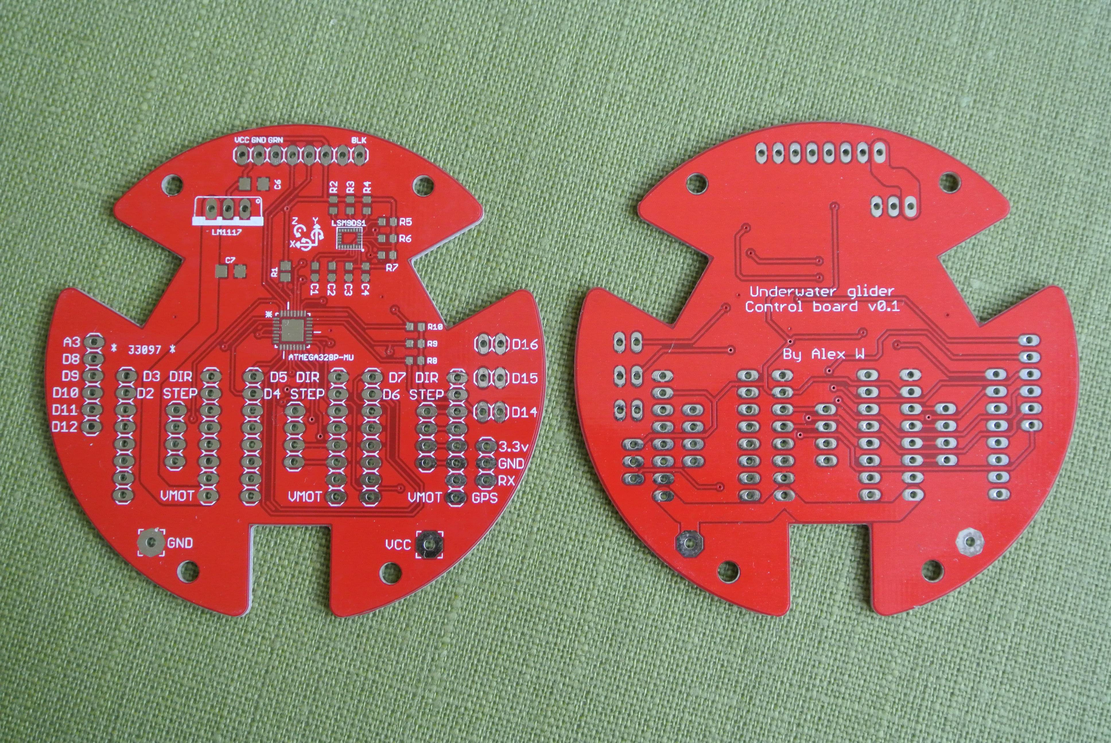
alexw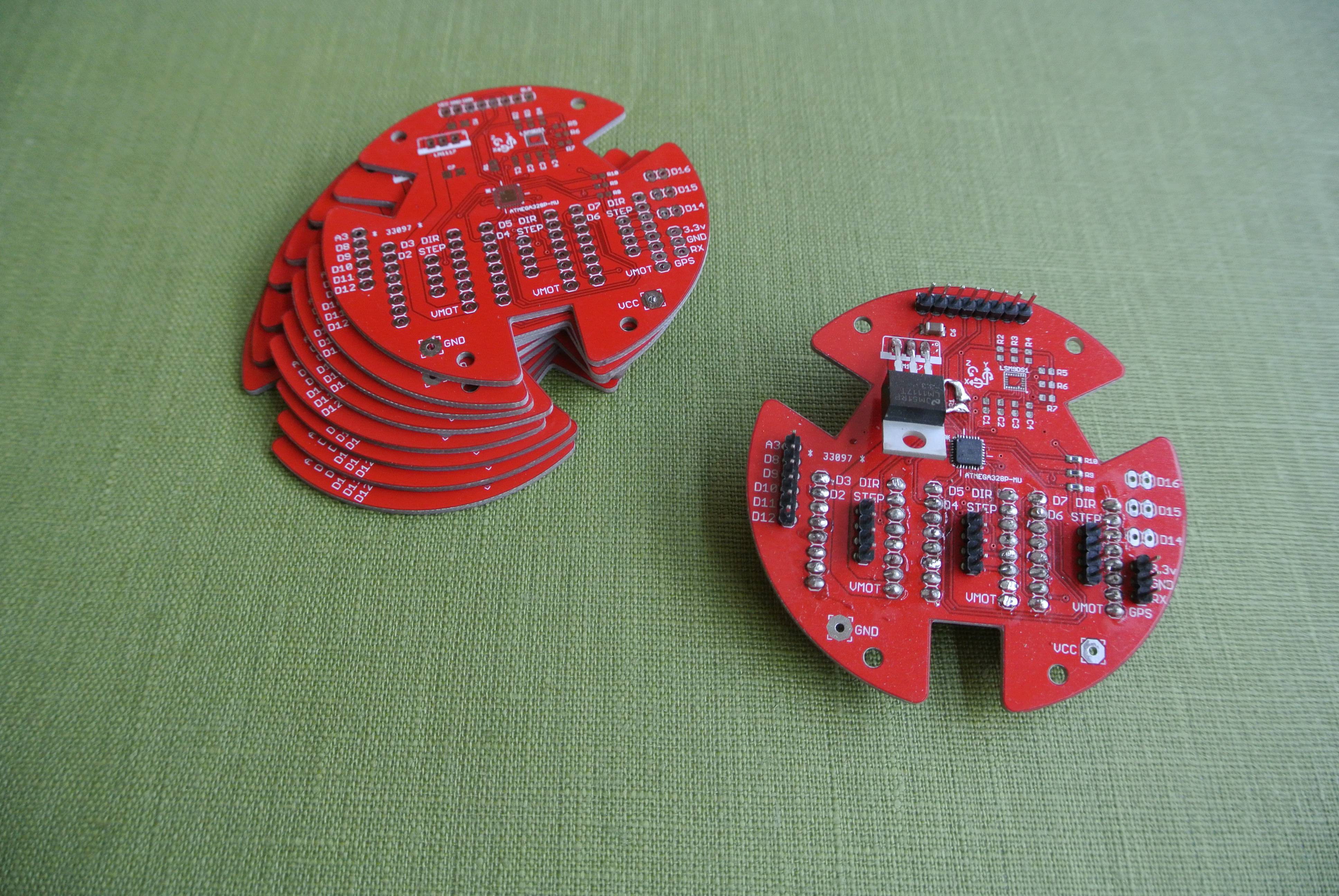 I received the
boards a few days ago and as I had already purchased the surface
mount components, I was able to produce a partially assembled board
relatively quickly.
I received the
boards a few days ago and as I had already purchased the surface
mount components, I was able to produce a partially assembled board
relatively quickly.
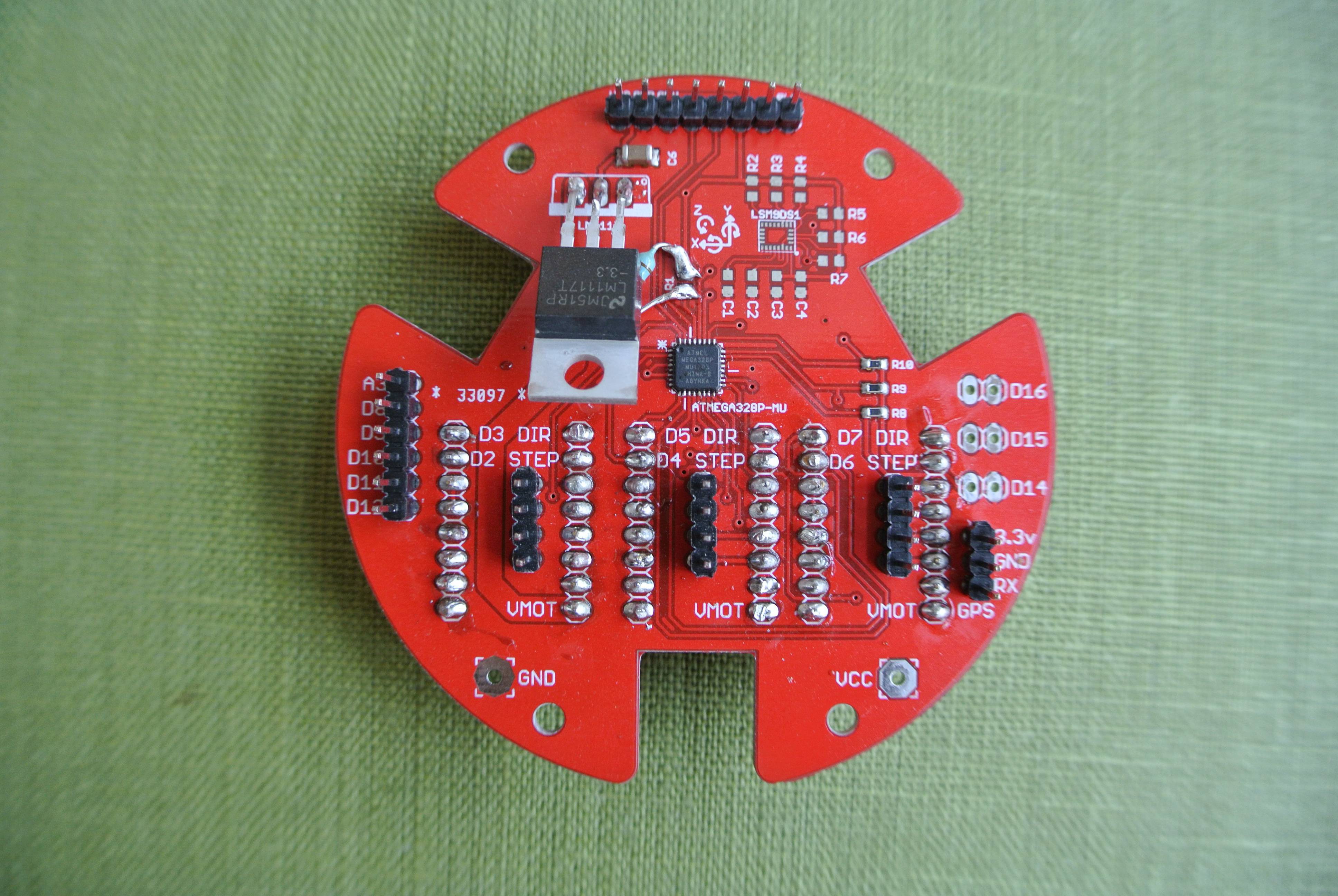
I soldered the surface mount components using my
trusty hot plate, which seemed to do a good job on the 0.45mm pitch atmega QFN package. The power regulator, resistor and headers were hand soldered. The resistor is due to a design error using an incorrect resistor package size and will be corrected for the next board revision.
 The board pictured does not have the IMU soldered on as I wanted to test the microprocessor first (flash firmware and simple stepper motor control), as the IMUs are relatively expensive (~£6 for 1). Once I have validated the microcontroller circuit, I will assemble another board with all the components.
This is what the board looks like with the three stepper motor drivers attached: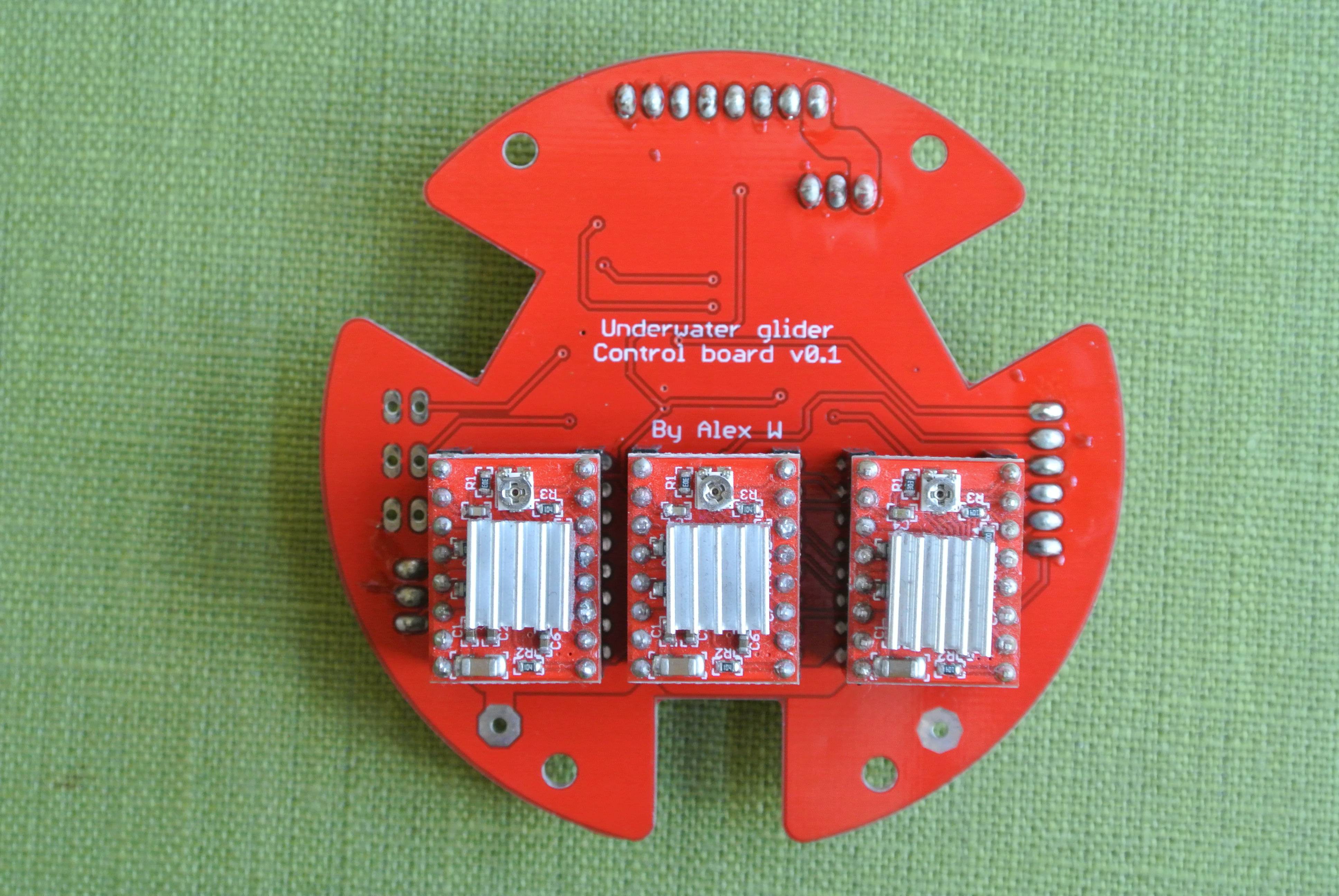
The next step is flashing the atmega and porting over the control software and making the glider standalone. I also plan on publishing an update concerning water sealing soon.
Discussions
Become a Hackaday.io Member
Create an account to leave a comment. Already have an account? Log In.