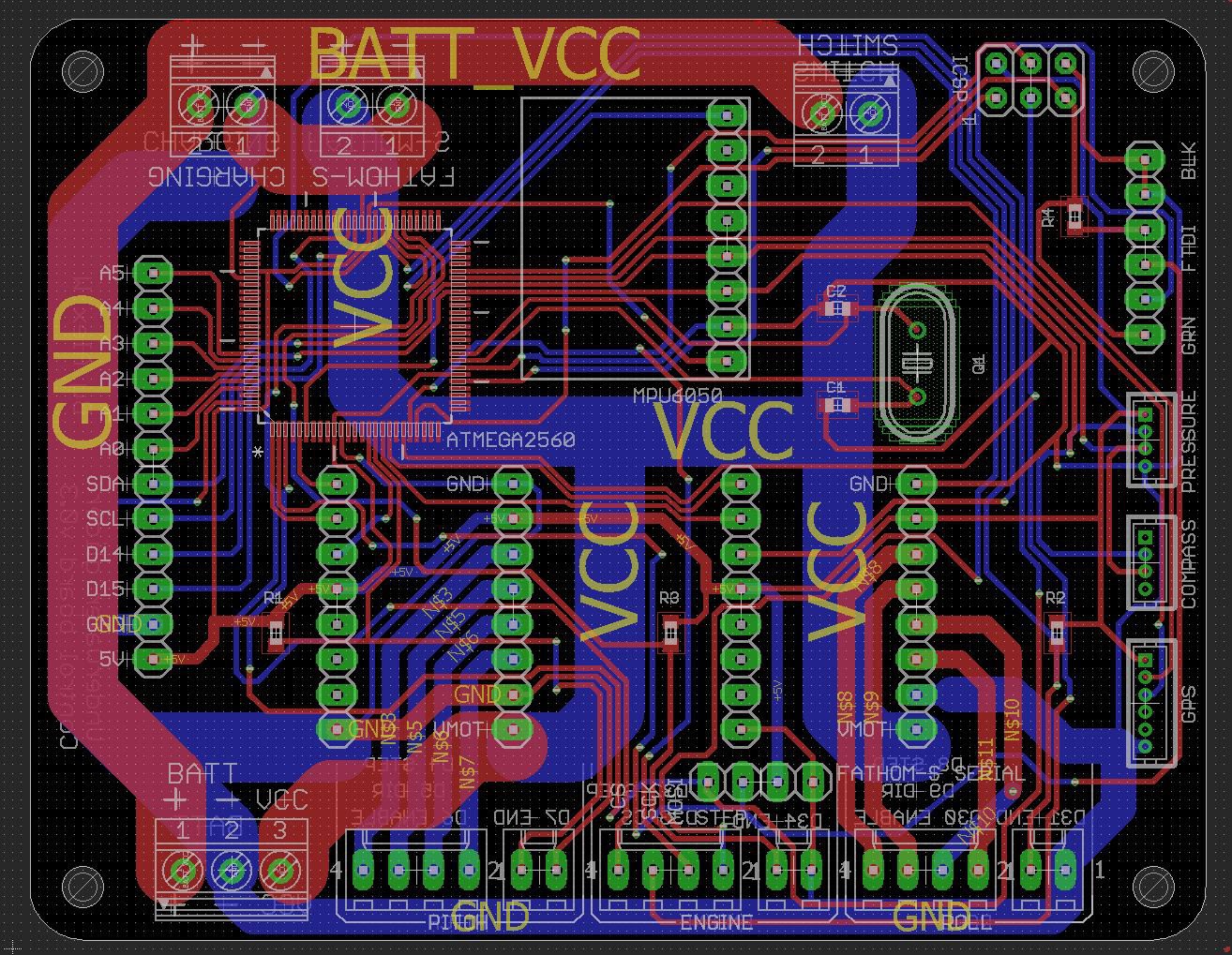
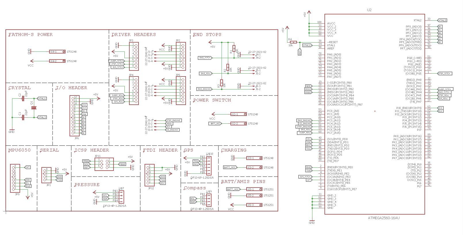
Over the last few days I've updated the design for the control board, with two notable improvements. The first is the hook-up of the "enable" pins of the stepper motor drivers to the ATMEGA2560, so that it is possible to power down the drivers whilst not in use in order to maximise battery life. The other main update is the removal of the A4988 for the buoyancy engine stepper motor, instead sending signals to an AMIS-30543 stepper motor driver board, which is mounted at the front of the glider next to the buoyancy engine. The AMIS-30543 has a greater current capability (3A vs 1.8A) and uses the SPI communication to control current, sleep, etc. I made sure that the new PCB could fit lower down in the 4" enclosure, in order to accommodate a full Pixhawk 2.1 (the vertical height of the "Cube" meant that it previously wouldn't fit).


The PCBs are being manufactured by OSHpark and I should have some assembled boards by mid next week. As usual, all design files are in the development DropBox folder, in the Underwater_glider/glider_pcbs/Control_board/v0.3 directory.
Over the coming days I will be testing the buoyancy engine to potentially determine a working depth limit.
 alexw
alexw
Discussions
Become a Hackaday.io Member
Create an account to leave a comment. Already have an account? Log In.