 Michael Gardi
I thought a good place to start would be to get the LEM showing up on the screen. I started by taking a screen shot of the online playable Lunar Lander Game and blowing up just the LEM part. I'm not sure where the antialiasing is coming from on the screen shot but this is something that would be very difficult to do on the PDP-1.
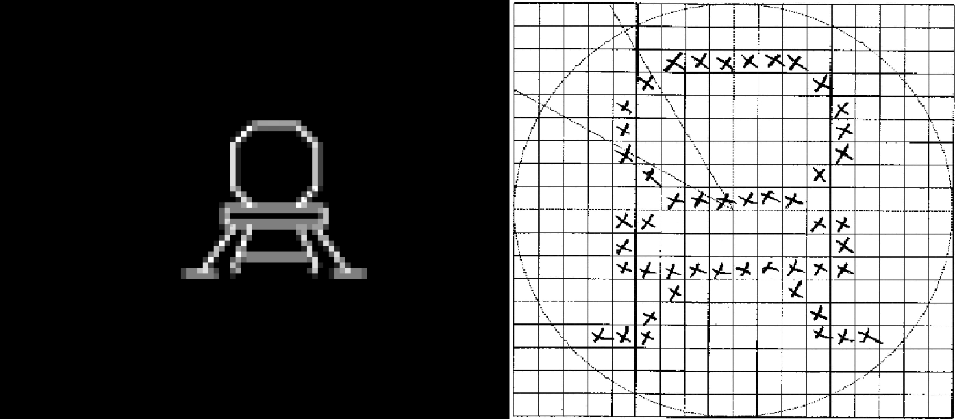
I went old school and grabbed a piece of graph paper and laid out the dots for my LEM. Since the PDP-1 has an 18-bit word size I thought and 18 x 18 bitmap would be a good size. Then I had a decision to make.
There were a couple of ways that I could render the LEM to the screen. I had read in the ICSS document where Norbert Landsteiner "compiled" small 5 x 7 character bitmaps directly into PDP-1 opcodes. I will dig deeper into this in a future "Display The State" log, but suffice it to say that this is a very efficient way of rendering a bitmap of dots to the screen. In fact I tried this out with a LEM bitmap and it worked very well. The problem is that for a single LEM image to be rendered the code generated was about 300 "words" long. I would need at a minimum 5 different versions of the LEM image (with the ship pointing in different directions) so call it 1500 words. The total available memory for the PDP-1 is 4096 words (without bank switching), so just the LEM images would occupy about 37% of the available memory.
The other way to render the LEM images is to add their bitmaps to the program as data and write a single routine to draw these bitmaps to the screen based on that data. When I wrote the code to draw these bitmaps it turned out to be 36 words long. So the total overhead of drawing the LEM this way was 18 word bitmaps x 5 bitmaps + 36 words of code or 126 words, less that 3% of the available memory. When I am done adding all the features I want to this Lunar Lander version, if I have enough memory left over, I will reconsider this decision.
I could have converted the bitmap to octal data (which is all that the macro assembler understands) by hand but where's the fun in that. What I did do is write a Python program to do it for me.
LEM = [
    ['-', '-', '-', '-', '-', '-', '-', '-', '-', '-', '-', '-', '-', '-', '-', '-', '-', '-'],
    ['-', '-', '-', '-', '-', '-', '-', '-', '-', '-', '-', '-', '-', '-', '-', '-', '-', '-'],
    ['-', '-', '-', '-', '-', '-', 'X', 'X', 'X', 'X', 'X', 'X', '-', '-', '-', '-', '-', '-'],
    ['-', '-', '-', '-', '-', 'X', '-', '-', '-', '-', '-', '-', 'X', '-', '-', '-', '-', '-'],
    ['-', '-', '-', '-', 'X', '-', '-', '-', '-', '-', '-', '-', '-', 'X', '-', '-', '-', '-'],
    ['-', '-', '-', '-', 'X', '-', '-', '-', '-', '-', '-', '-', '-', 'X', '-', '-', '-', '-'],
    ['-', '-', '-', '-', 'X', '-', '-', '-', '-', '-', '-', '-', '-', 'X', '-', '-', '-', '-'],
    ['-', '-', '-', '-', '-', 'X', '-', '-', '-', '-', '-', '-', 'X', '-', '-', '-', '-', '-'],
    ['-', '-', '-', '-', '-', '-', 'X', 'X', 'X', 'X', 'X', 'X', '-', '-', '-', '-', '-', '-'],
    ['-', '-', '-', '-', 'X', 'X', '-', '-', '-', '-', '-', '-', 'X', 'X', '-', '-', '-', '-'],
    ['-', '-', '-', '-', 'X', '-', '-', '-', '-', '-', '-', '-', '-', 'X', '-', '-', '-', '-'],
    ['-', '-', '-', '-', 'X', 'X', 'X', 'X', 'X', 'X', 'X', 'X', 'X', 'X', '-', '-', '-', '-'],
    ['-', '-', '-', '-', '-', '-', 'X', '-', '-', '-', '-', 'X', '-', '-', '-', '-', '-', '-'],
    ['-', '-', '-', '-', '-', 'X', '-', '-', '-', '-', '-', '-', 'X', '-', '-', '-', '-', '-'],
    ['-', '-', '-', 'X', 'X', 'X', '-', '-', '-', '-', '-', '-', 'X', 'X', 'X', '-', '-', '-'],
    ['-', '-', '-', '-', '-', '-', '-', '-', '-', '-', '-', '-', '-', '-', '-', '-', '-', '-'],
    ['-', '-', '-', '-', '-', '-', '-', '-', '-', '-', '-', '-', '-', '-', '-', '-', '-', '-']
]

# Encode the LEM bitmap as a series of 18 18-bit words in octal format.
for r_idx, row in enumerate(LEM):
    # Process the next row.
    row_value = 0
    col_pos = 0b100000000000000000
    for c_idx, char in enumerate(row):
        if char == 'X':
            row_value = row_value | col_pos
        col_pos = col_pos >> 1
    #print(bin(row_value)[2:].zfill(18))
    print(str(oct(row_value)[2:]).zfill(6))
And the result is:
007700
010040
020020
020020
020020
010040
007700
030060
020020
037760
004100
010040
070070
0
I removed leading empty words (all zeros) and left a single 0 at the end as an end-of-data marker.
There is some setup code from the snippet below, but here is the meat of the LEM drawing routine.
/ Draw the LEM based on an 18-bit by 18 word bitmap.
lt1,    jmp .
lm1,    dap lt1

/ ... Setup stuff goes here. ...

/ Draw LEM.
lbn,    lac .                  / Get the next row from the LEM bitmap.
        sza i                  / Is row value 0?
        jmp lt1                /  Yes - Then done drawing the LEM.

/ Process the next row of the bitmap.
        dac bmr                /   No - Save the next row value.
        lac (400000            / Setup the first (leftmost bit) to look at.
        dac bit

nb0,    lac bit                / Get the current bit position.
        and bmr                / Check to see if bit is to be displayed.
        sza i                  / Is bit position value zero?
        jmp nb1                /  Yes - Get ready for next bit.

        lac bsx                /   No - Draw the bit.
        lio bsy
        dpy-i

nb1,    lac bit                / Check to see if all the bits have been processed.
        sad (1                 / Is bit in last position?
        jmp nrw                /  Yes - Get ready for next row.

        lac bit                /   No - Shift the test bit right one place.
        rar 1s
        dac bit

        lac bsx                / Advance screen x.
        add scl
        dac bsx
        jmp nb0                / Do the next bit.

nrw,    lac lbn                / Point to the next row in the bitmap.
        add (1
        dac lbn

        lac bsy                / Advance screen y.
        sub scl
        dac bsy

        lac scx                / Reset screen x.
        sub (4400
        bsx

        lac (400000            / Setup the first (leftmost bit) to look at.
        dac bit
        jmp lbn
My initial thought was to have seven positions for the LEM at 0, 30, 60, 90, 120, 150, and 180 degrees where at 0 the LEM points directly left, 90 directly up, 180 directly right, with four in-between stops. When I tried creating bitmaps for 30 and 60 degree LEMS they looked awful. An 18 x18 pixel bitmap just does not have the fidelity handle such small changes. 45 degrees does looks good though so I will at least for now have five directions. I may have to compensate for the lack of 30 and 60 degree rotations some other way. Perhaps variable thrust?
Again I took an old school approach to creating the 45 degree bitmap.
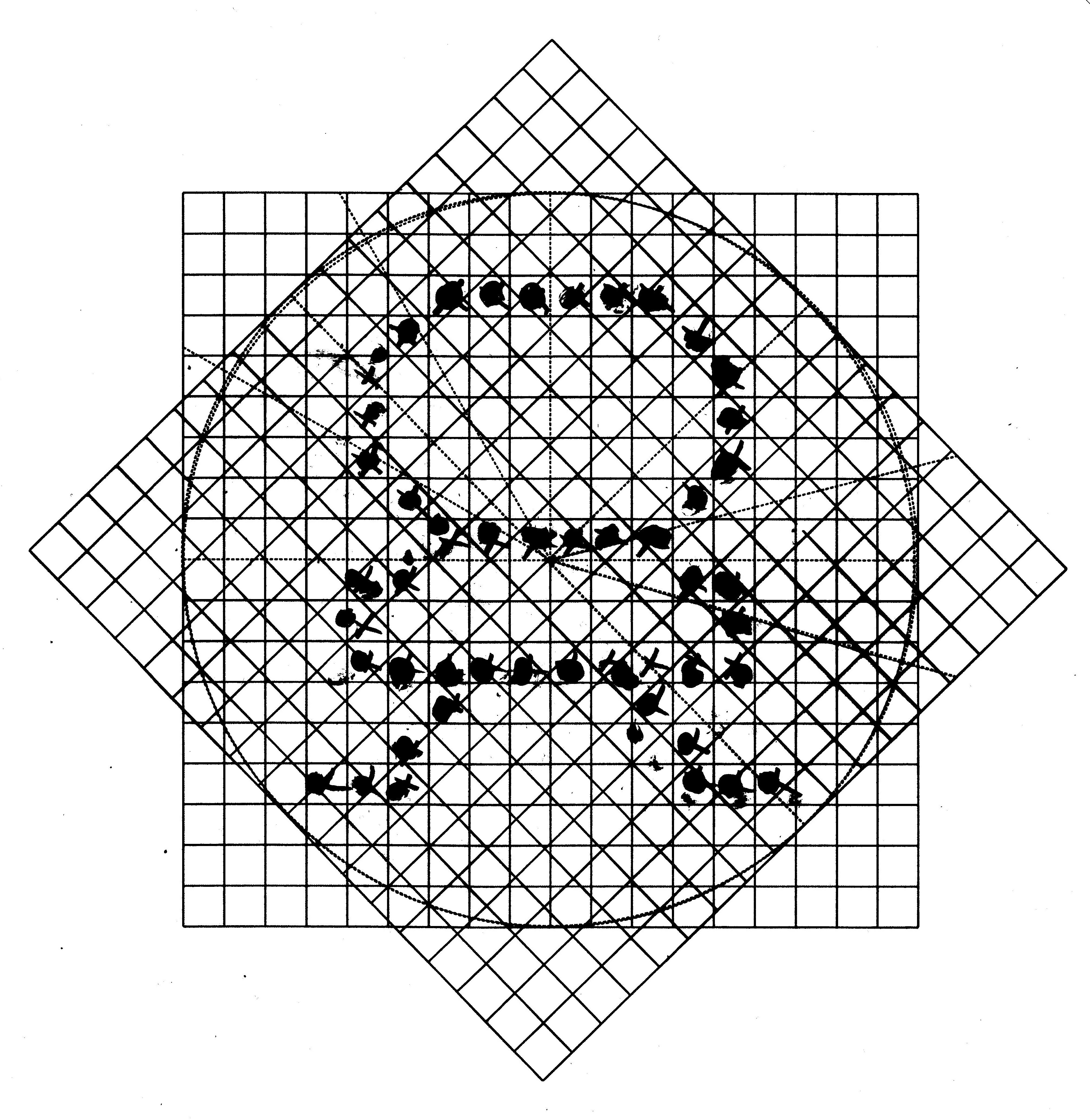
I printed the 18 x 18 grid onto a transparency then laid it on top of the LEM I had already done but at 45 degrees. Then I marked the squares that most closely matched the original's pixels. With a few tweaks to my Python program I had bitmap data for the LED in all five orientations.
If you revisit the video in the What I Have So Far log you can see that the LEM transitions pretty smoothly when rotated.
Discussions
Become a Hackaday.io Member
Create an account to leave a comment. Already have an account? Log In.