 Ai-Thinker
Project Card
- Core Brain: WV01-32S Module x1
- Power Heart: DRV8833 Dual-Channel Motor Driver Board x2
- Soul Components: Micro Wheels + Geared Motors x4
- Battery Life: 4.2V 2500mAh 18650 Li-ion Battery (Extra-Long Run)
- Control Methods: Infrared Control + Voice Interaction
- Ease of Use: ★★☆☆☆ (Just get your hands on it)
Hardware List
Component Name | Specific Model/Specification | Purchase Platform |
Main Control | WV01-32S Module | Ai-Thinker |
Motor Driver Board | DRV8833 Module | Taobao |
Mecanum Wheel Assembly | Mecanum Wheel + 6V Geared Motor | Pinduoduo |
Power Supply | 4.2V Lithium Battery | - |
Chassis/Shell | PCB used directly as chassis, ugly shell from 3D printing | PCB uses 1.6mm thickness (length >10cm, not free at JLCPCB) |
PCB Soldering
After lengthy wait, boards finally arrived. Time to solder!
Not many components, so it was a breeze! The trickiest soldering was definitely those LEDs.
As far as I know, I know nothing. If nothing goes wrong, something is bound to go wrong. The motor driver's inputs and outputs were reversed (utterly baffling – I must have drawn the schematic with my eyes closed to miss such an obvious error).
No choice but to fly-wire it. Agony, agony, agony!!!
Car Body Shell
Modelled using Fusion360 – yes, you read that right, it's a Huolala!
Coupling: Connects the micro wheel to the motor.
The casing was printed using transparent PETG. With the weather turning colder, the heated bed wasn't gripping well, causing supports to keep falling off. After multiple prints, it finally succeeded.
Assembly
Prepare the printed coupling, snap-fit bracket, and gear motor.
1. Mounting motor/magnetic wheel: Snap the gear motor into the 3D-printed bracket, then secure it to the PCB with screws. Note the magnetic wheel's orientation: install it in the X direction, ensuring correct placement.
2. Driver board/main controller: Insert the motor driver board and WV01 core board into the female header. Ensure correct orientation. As the battery will be mounted on the reverse side, trim any protruding sections beforehand.
Firmware Burning/Debugging: Employ the Boliu serial burning tool to flash the vehicle firmware onto the board. Subsequently reset the system to verify controllability after network configuration. Should anomalies arise, utilise the serial monitor to examine output data for troubleshooting.
Core Code
Secondary development based on the WV01 SDK framework, with the core focus being the implementation of the wheeled robot's ‘motion logic’ – controlling the direction of all four wheels. Various combinations enable operations such as rotation, translation, diagonal movement, and turning in circles!
Currently set to four speed settings. The gear motor selected by the previous poster isn't particularly fast (don't ask where I got it from).
The control of the Maileun trolley is achieved through this method, encompassing movements such as forward, backward, left, right, and turning in circles.
Add an MCP method for vehicle movement and speed control, enabling AI to manage the vehicle's motion and velocity.
Register MCP tool
Implemented infrared control functionality for the vehicle, which parses received NEC codes to execute corresponding movement operations.
Given the limited resources of the WV01, we can comment out the OTA section of the code to free up space for our thread.
Note: The WV01-32S has 5 PWM channels, with 4 currently in use. Each DRV8833 is controlled by one PWM pin and one I/O port. Forward and reverse utilise two distinct damping...
Read more »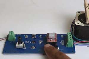
 Mrinnovative
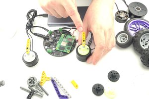
 Artur Majtczak
 Arshmah Shahkar
 Danny FR