Arnov Sharma
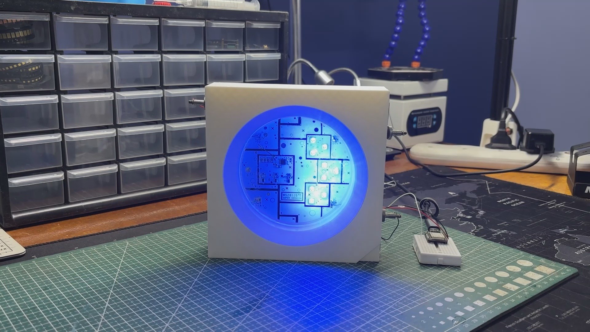
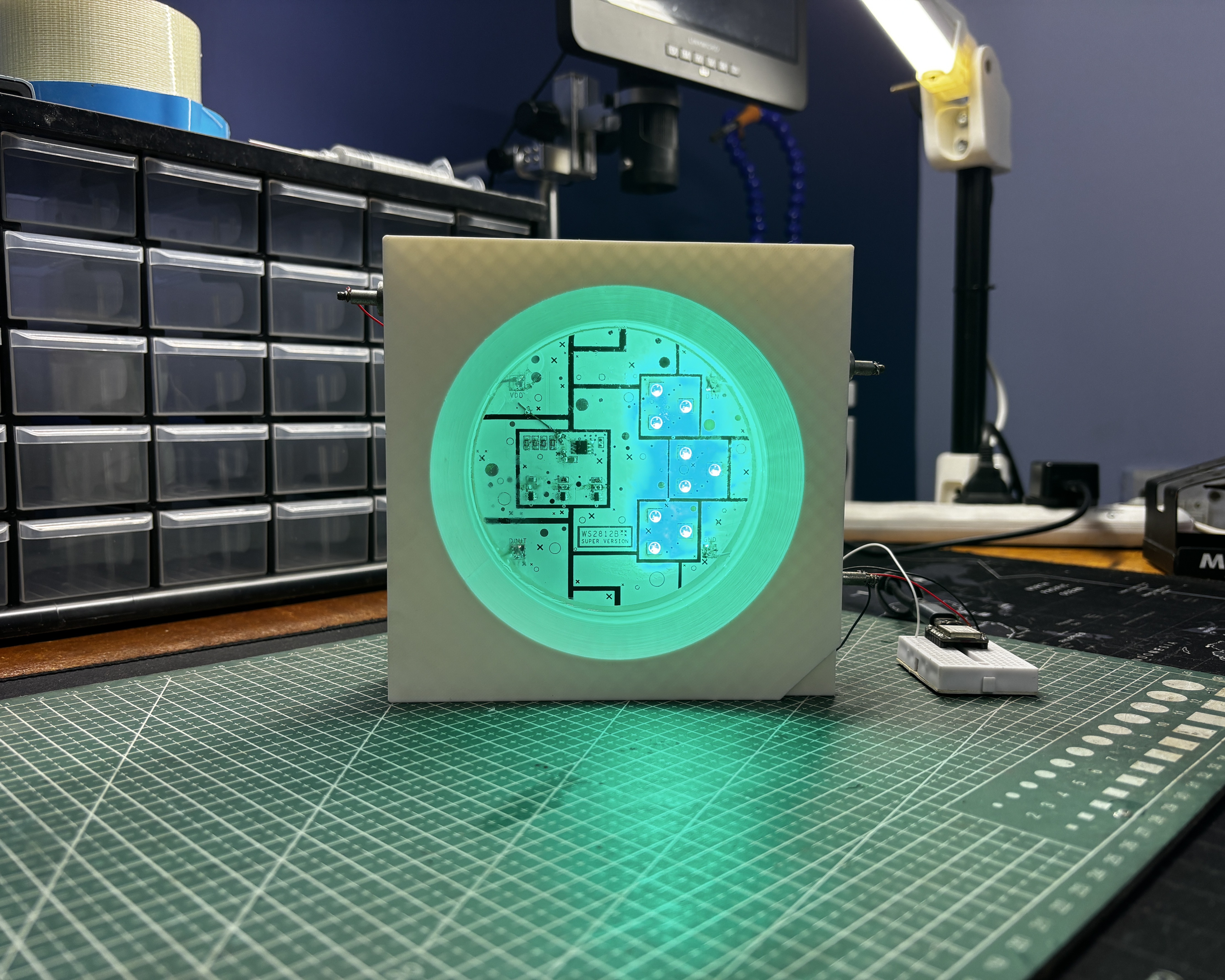
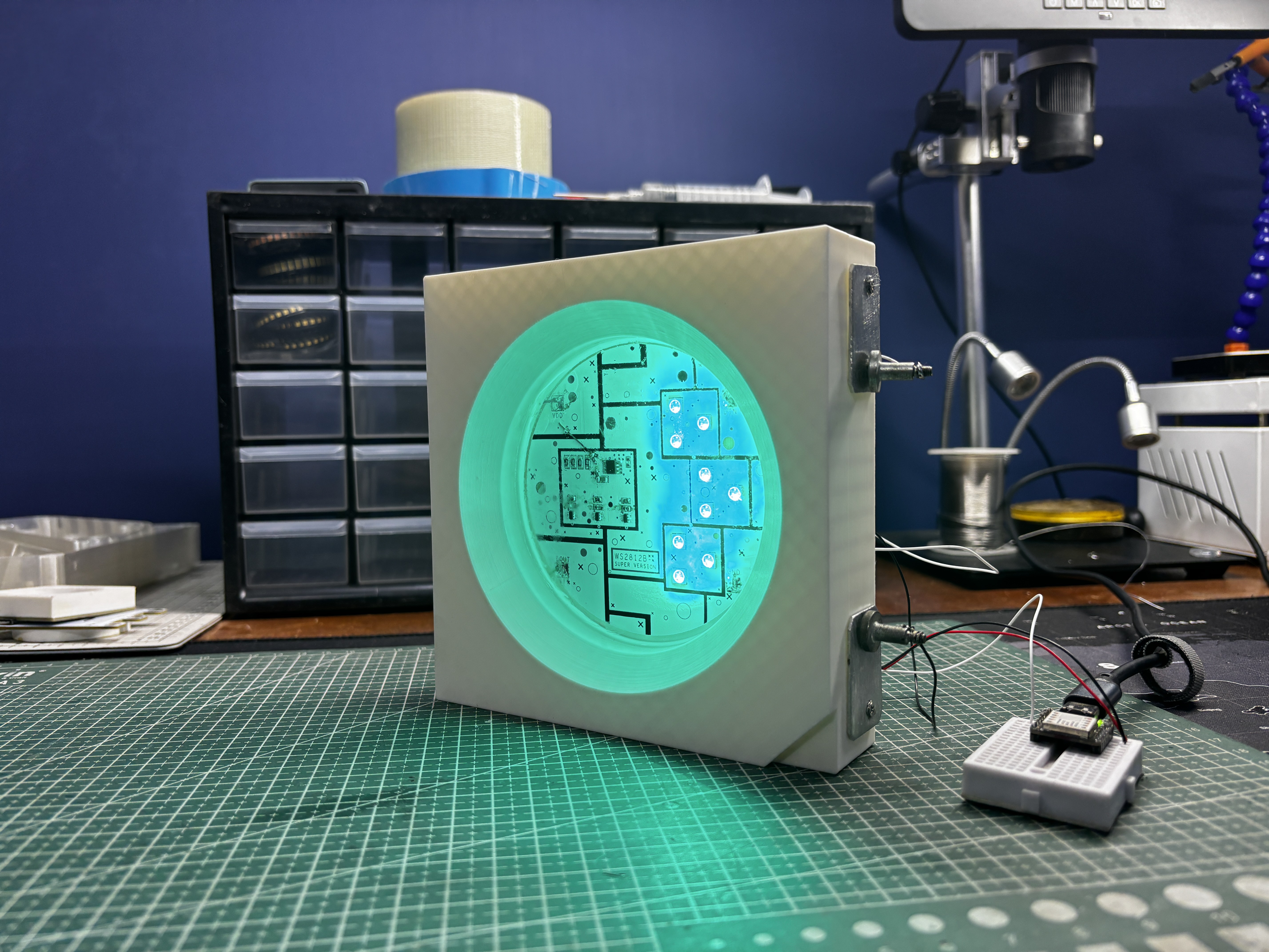
To complete the look, we poured clear epoxy over the electronics, just like how the real WS2812B encapsulates its RGB LEDs and addressable chip inside a 5050 epoxy package.
WS2812B ADDRESSABLE LED
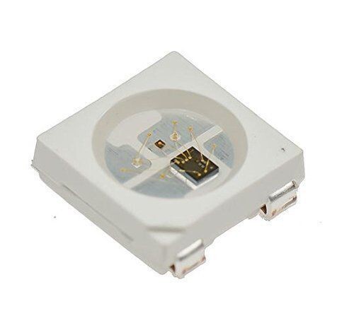
Before starting the project, let’s have a closer look at the WS2812B addressable LED. This is a component that I really enjoy using in my projects; in fact, I’ve made many builds based around WS2812B.
One of the main reasons is that, unlike a regular RGB LED that has a common anode or cathode pin along with three separate pins that control the R, G, and B channels, the WS2812B features a single data input pin that handles everything.
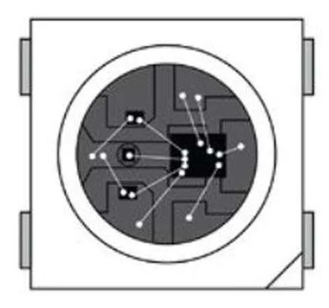
Inside the tiny 5050 package, the WS2812B actually contains three LED chips (red, green, and blue) and a built-in constant-current LED driver IC. This internal driver interprets a high-speed 800 kHz data signal, decodes color information for 24-bit RGB (8 bits per channel), and sets the brightness of each LED accordingly.
Another interesting detail is that WS2812B LEDs are designed to be daisy-chained: the Data Out pin automatically forwards the remaining data to the next LED in the chain. This means you can control hundreds or even thousands of LEDs using just a single microcontroller pin.
They also support PWM at around 400–800 Hz, which provides smooth color transitions, animations, and brightness control without visible flicker. Power-wise, each LED can draw up to 60 mA at full white (20 mA per channel), although most animations use much less.
3D DESIGN
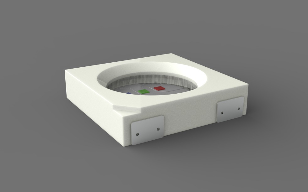
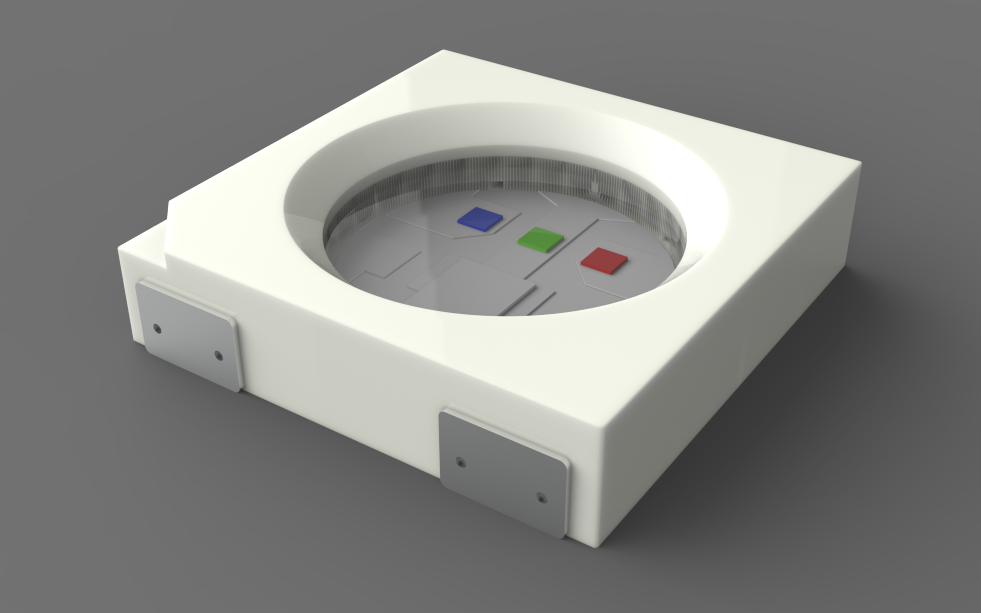
We began the project by finding a clear top-view image of the WS2812B LED. This image was imported into Fusion 360 using the Canvas feature, and with the Calibrate tool we set the width and height to 150 mm, which is exactly 30 times larger than the real WS2812B.
After scaling, we traced the outline directly over the canvas reference to recreate the entire LED model within minutes.
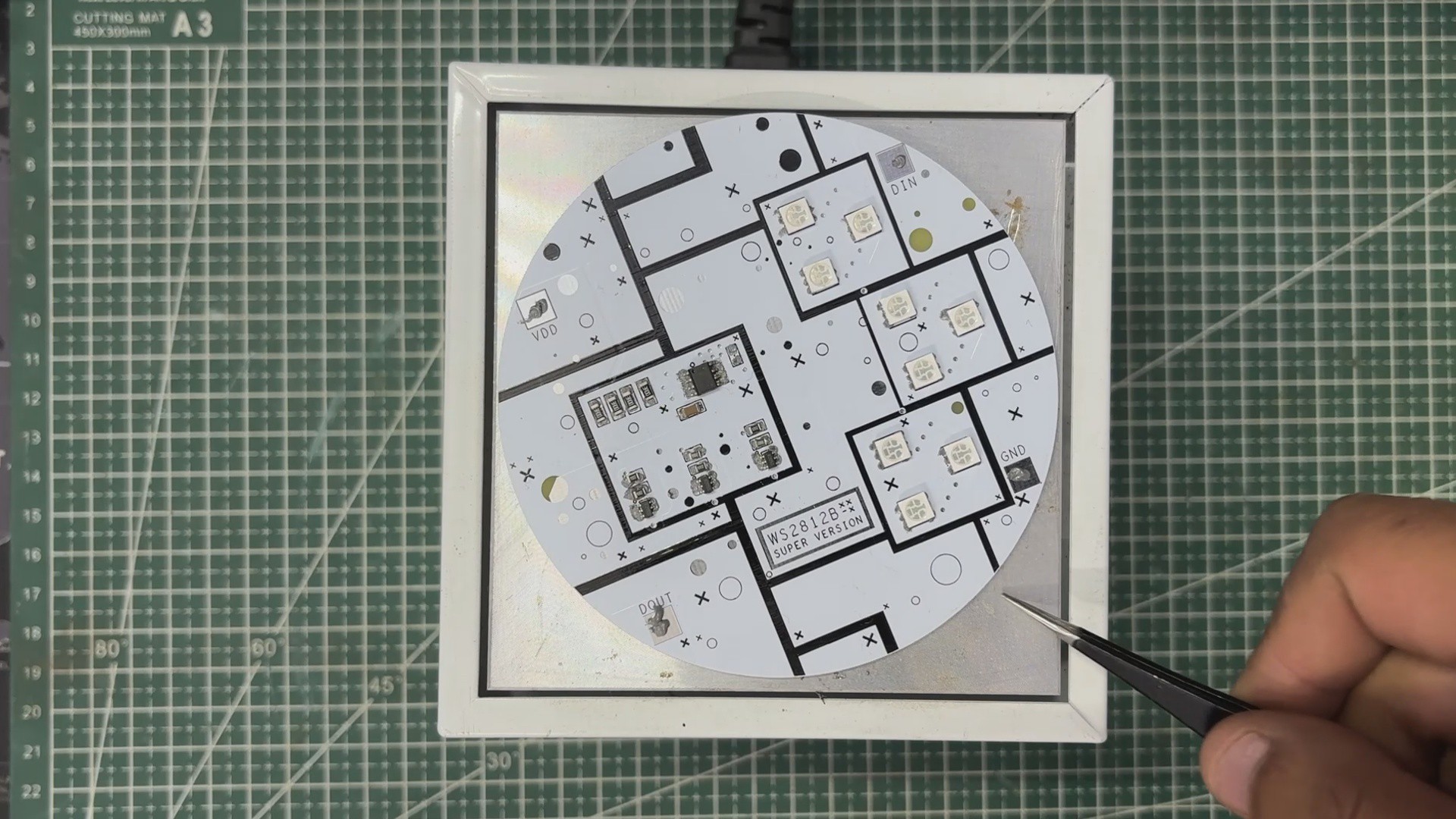
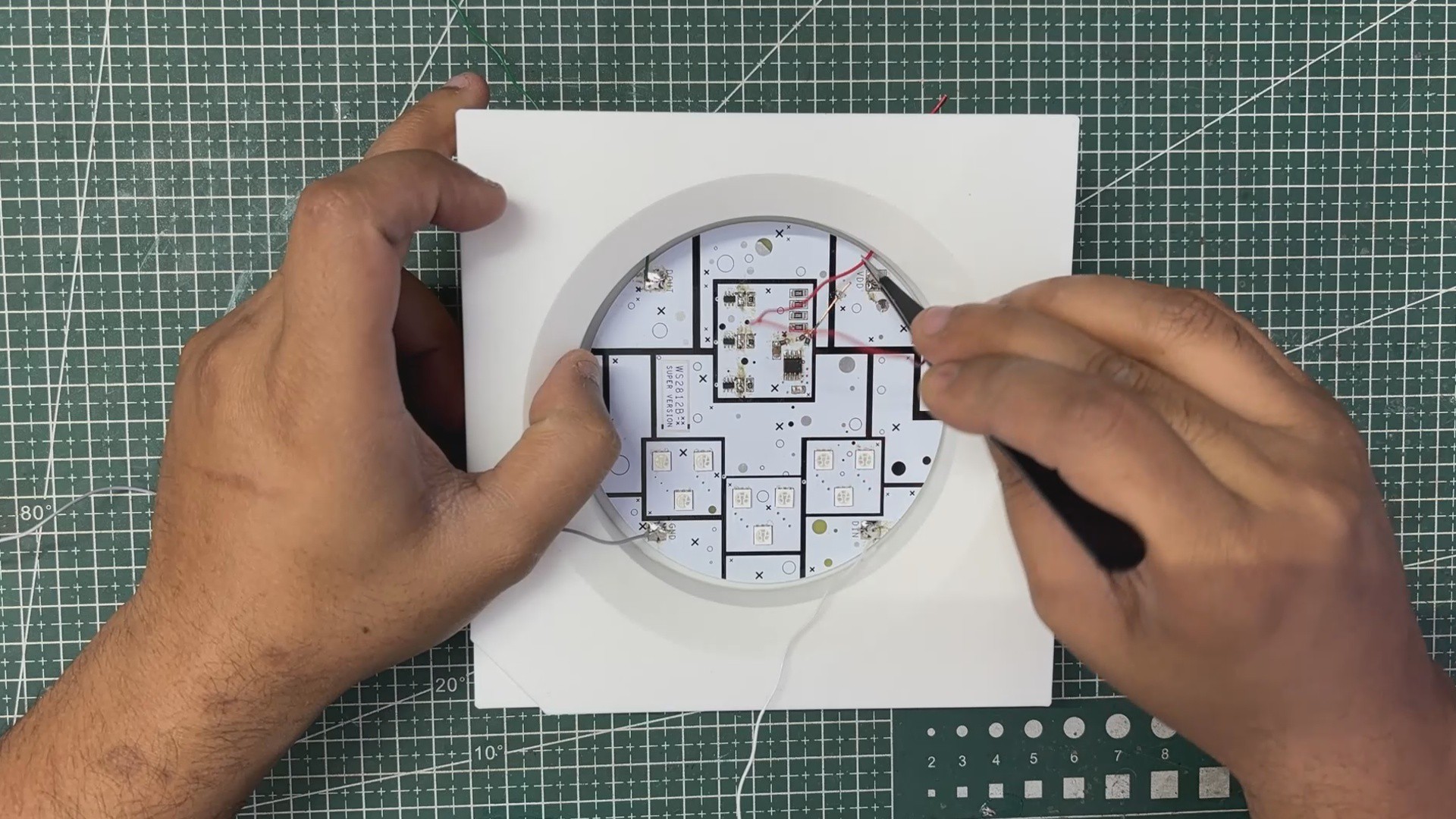
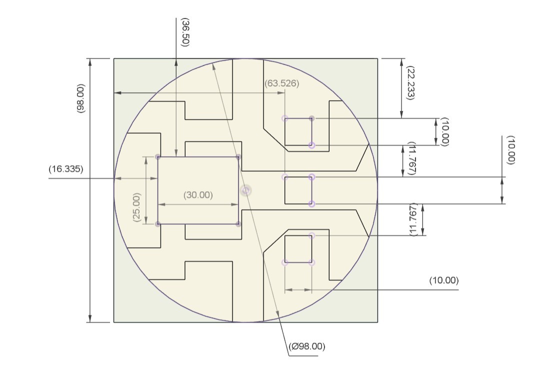
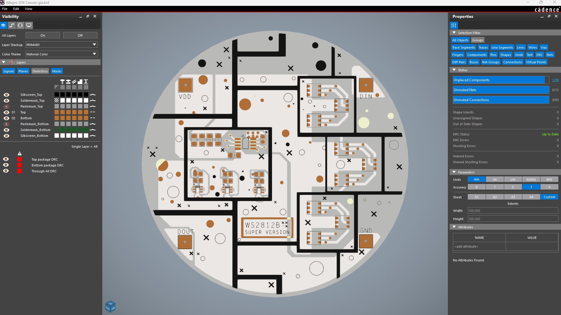
In the middle, where the real WS2812B houses its components, we added a 98 mm circular PCB and modeled simple SMD parts that resemble the internal elements of the original LED. This reference layout helped us later position the RGB LEDs and the WS2811 control IC accurately on the actual PCB.
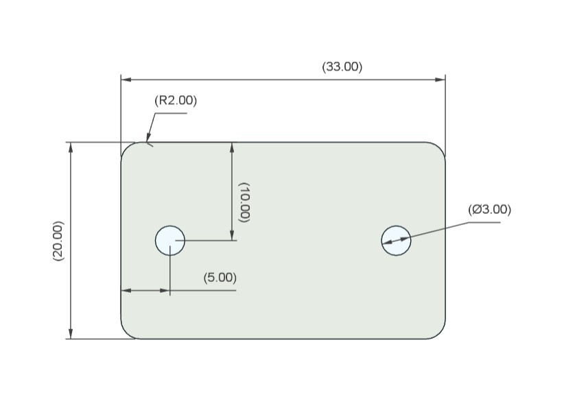
We also designed functional terminals just like the pads of a real WS2812B. For this, we used aluminum sheet pieces that were cut to shape following the dimensions from our CAD drawing. Each terminal piece was secured using two screws, and wires can be connected directly through these screw holes, effectively turning the aluminum pieces into VCC, GND, and DIN terminals for controlling the Giant Neopixel. After cutting the sheet with a hand tool, we drilled mounting holes and lightly sanded the pieces to give them a more realistic terminal-like finish.
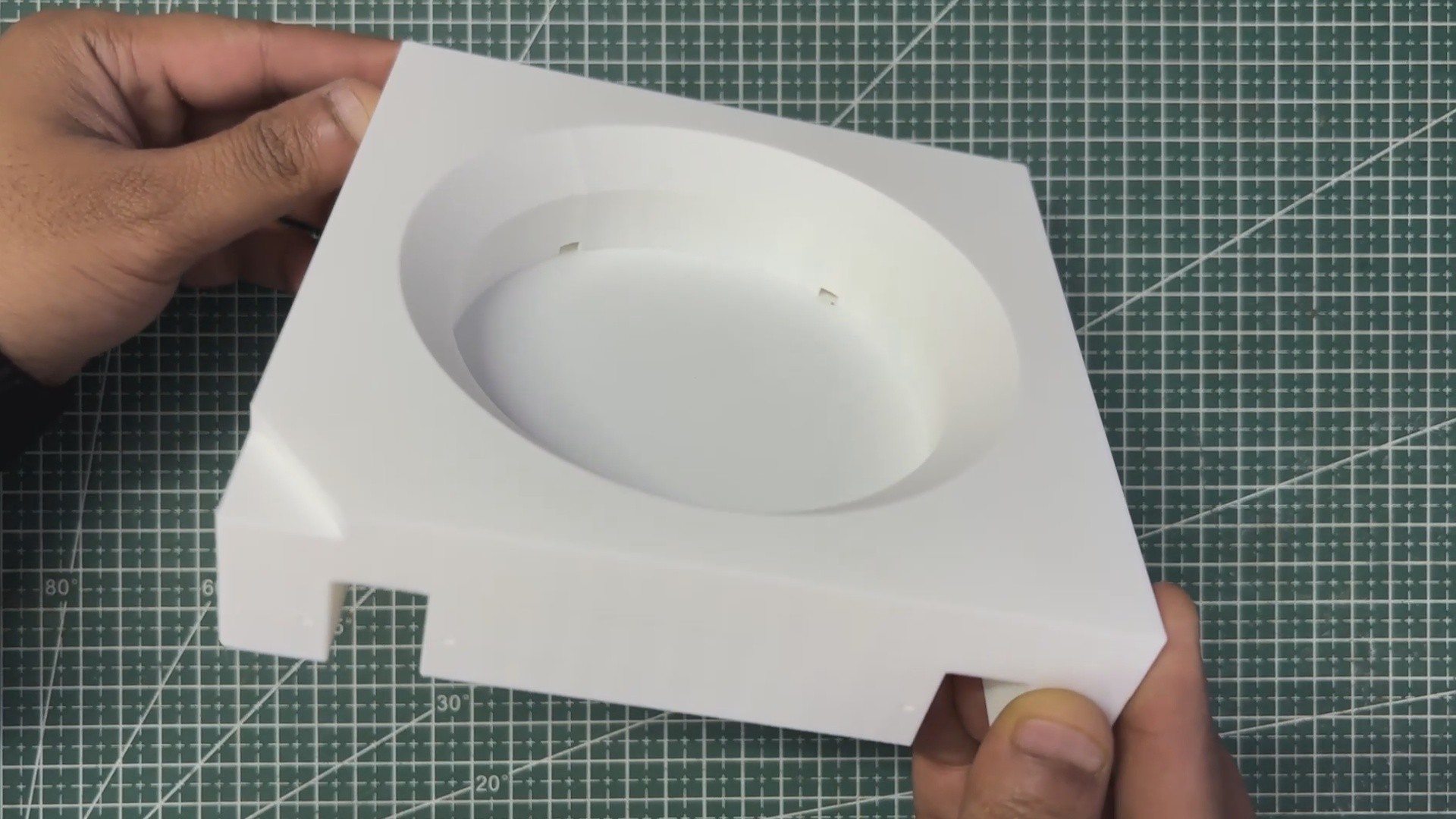
Once the 3D body of the LED was complete, we exported it as a mesh file and 3D printed the enclosure on our Anycubic Kobra S1 using white high-speed PLA.
PCB DESIGN
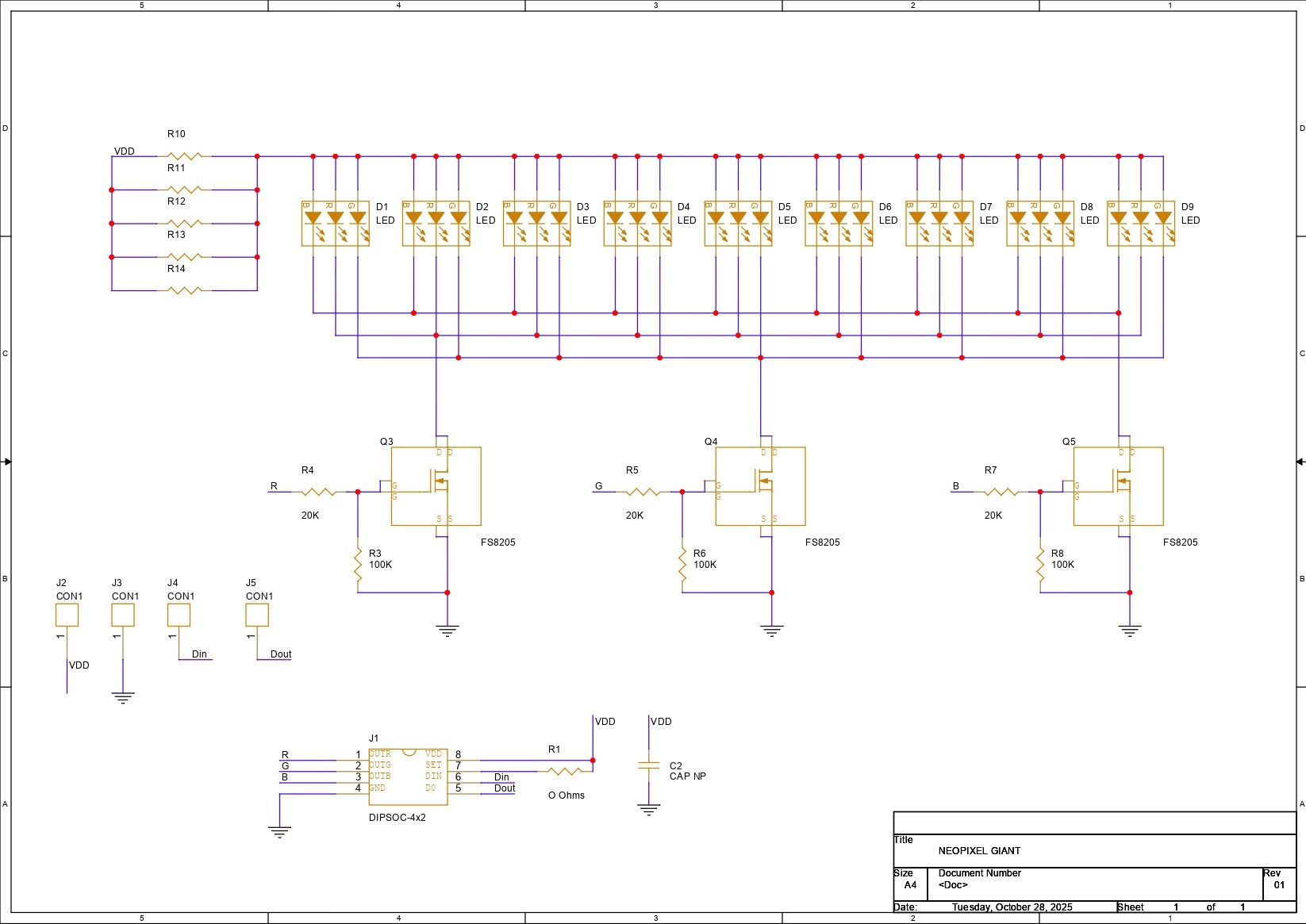
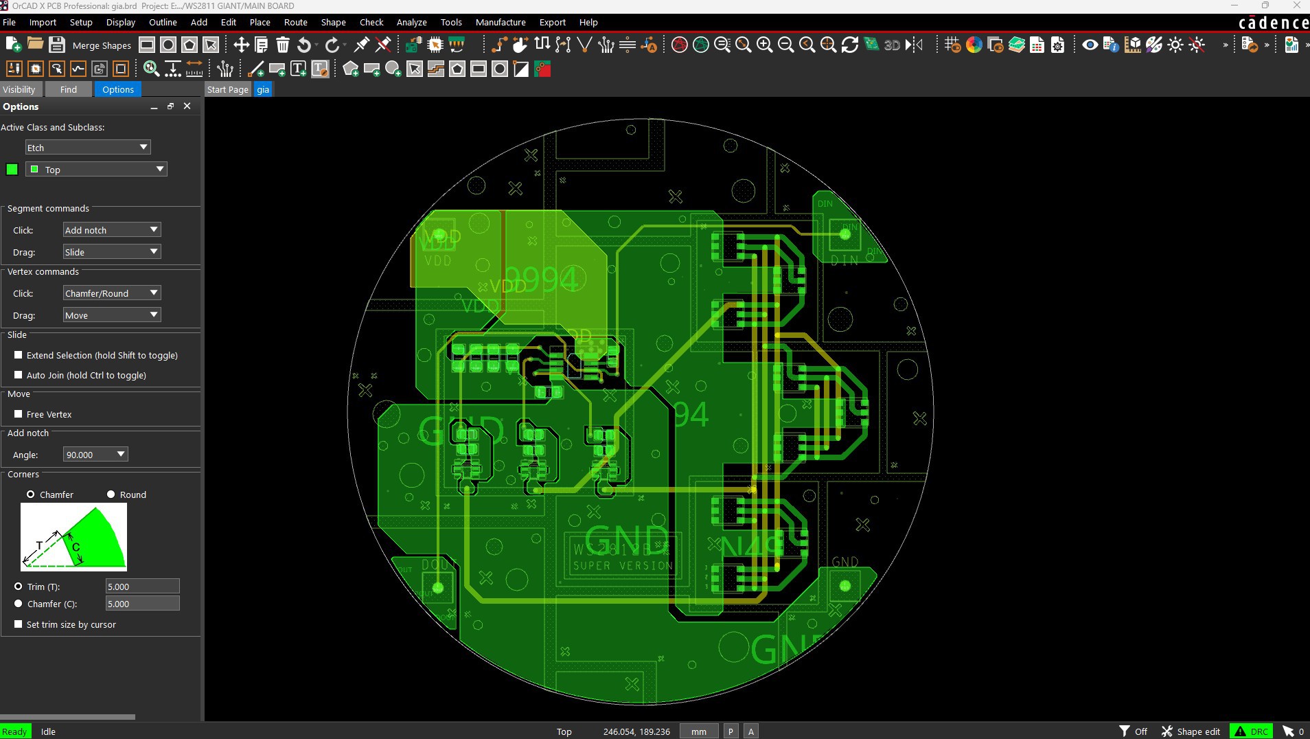
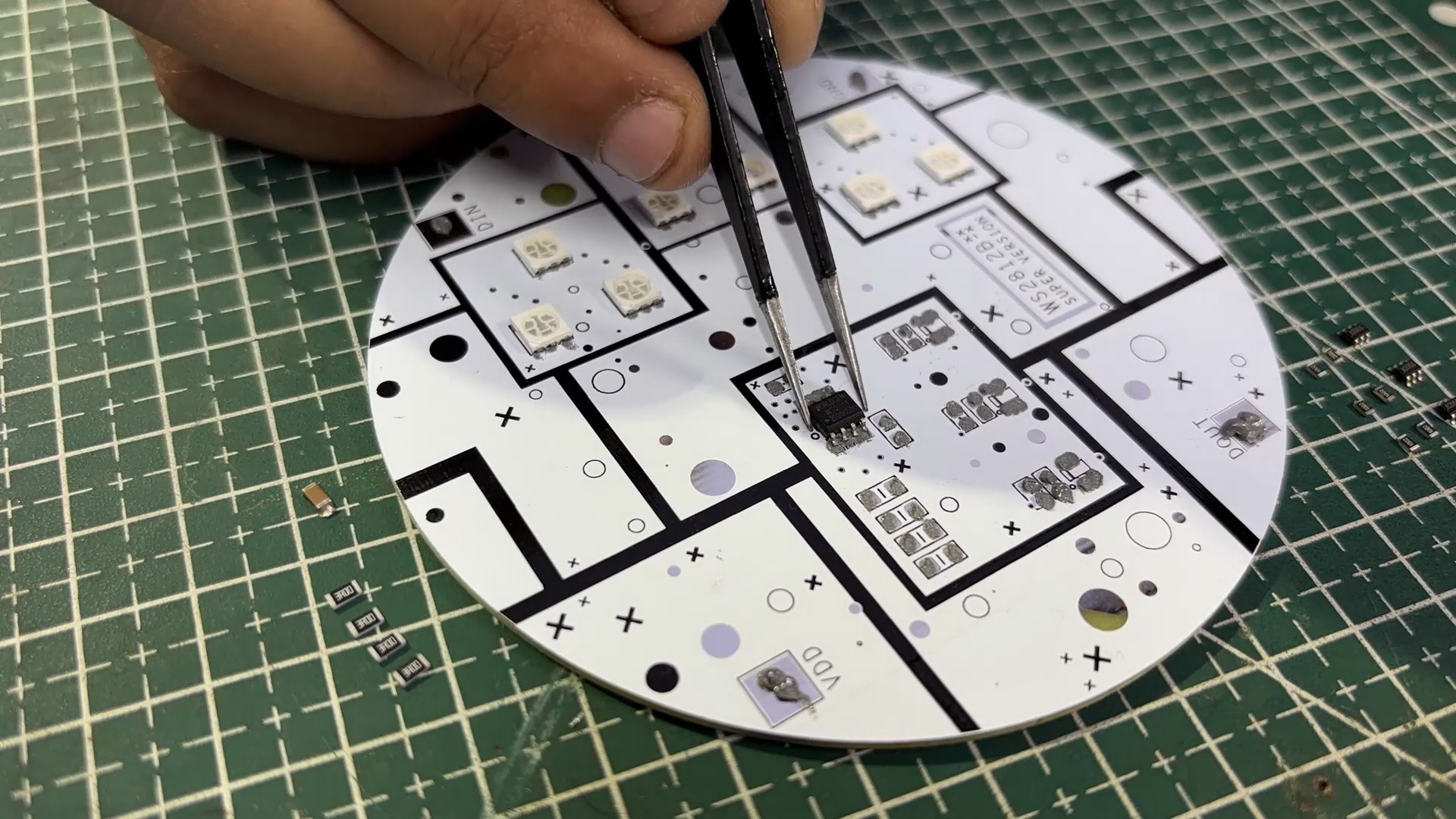
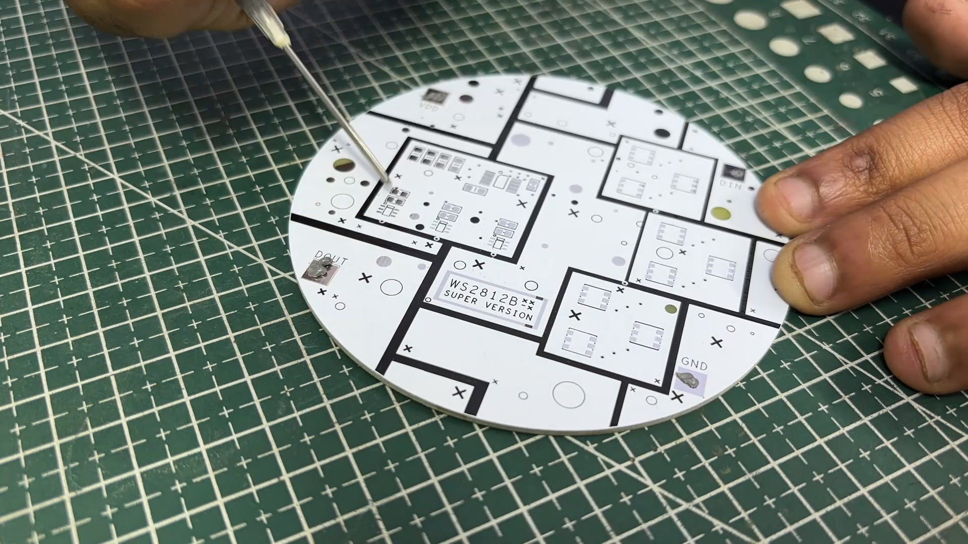
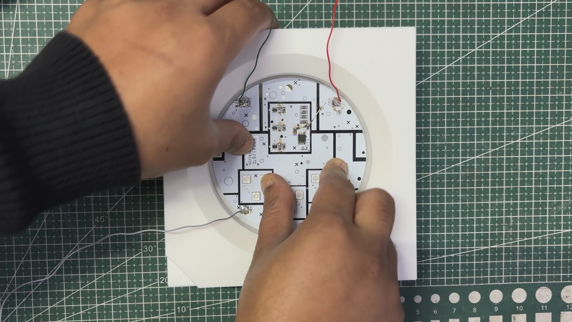
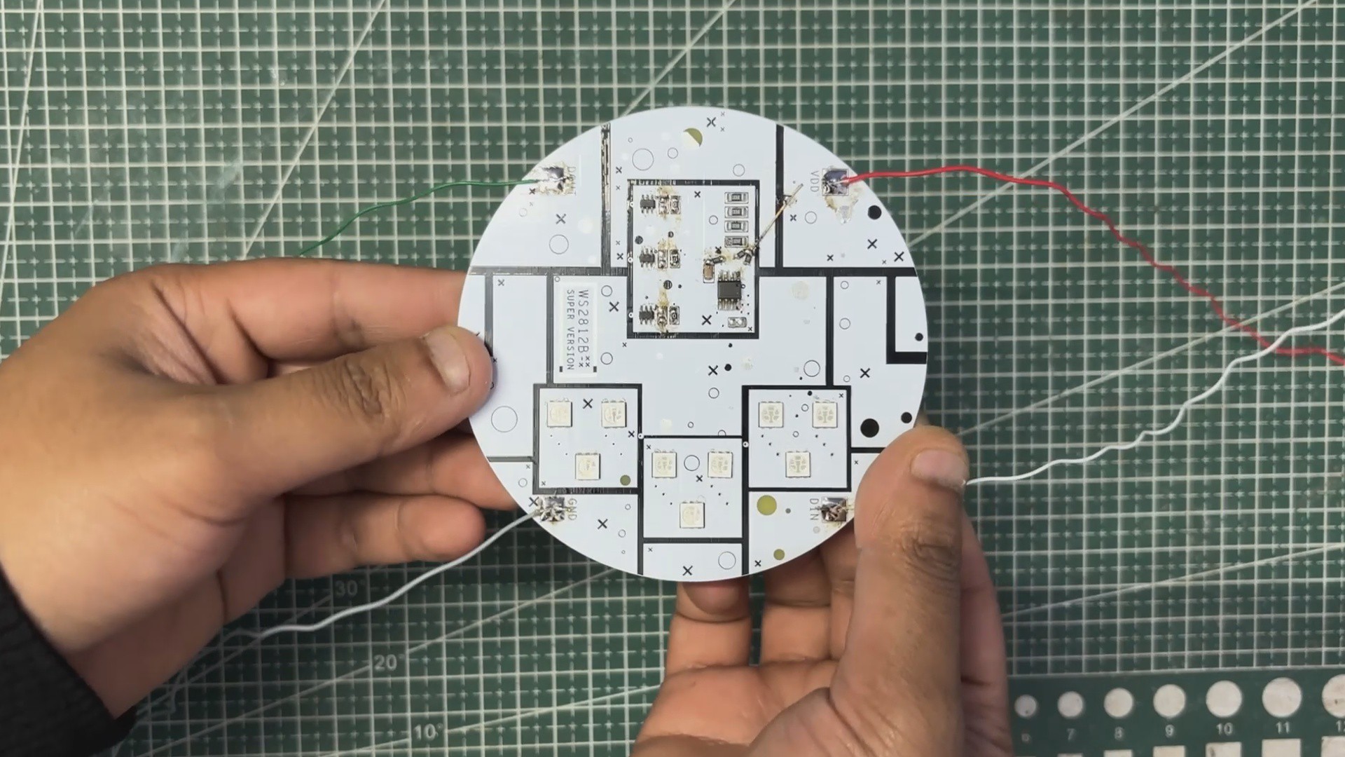
We started the PCB design process by preparing the schematic for this project. The circuit uses the minimal configuration of the WS2811 IC, paired with three MOSFETs used as switching stages. For the MOSFETs, we selected the 8205S N-channel dual MOSFET IC, which we used to control the red, green, and blue channels.
Our design includes nine 5050 RGB LEDs. All LED anodes are tied to VCC, while their cathodes are grouped by color:
- All Red cathodes are connected in parallel to the first MOSFET
- All Green cathodes are connected in parallel to the second MOSFET
- All Blue cathodes are connected in parallel to the third MOSFET
The gates of the three MOSFETs are driven by the R, G, and B outputs of the WS2811 IC, each connected through a 10 kΩ gate resistor. Using MOSFETs allows us to drive much higher currents than the WS2811 could handle directly, which makes the entire LED assembly significantly brighter.
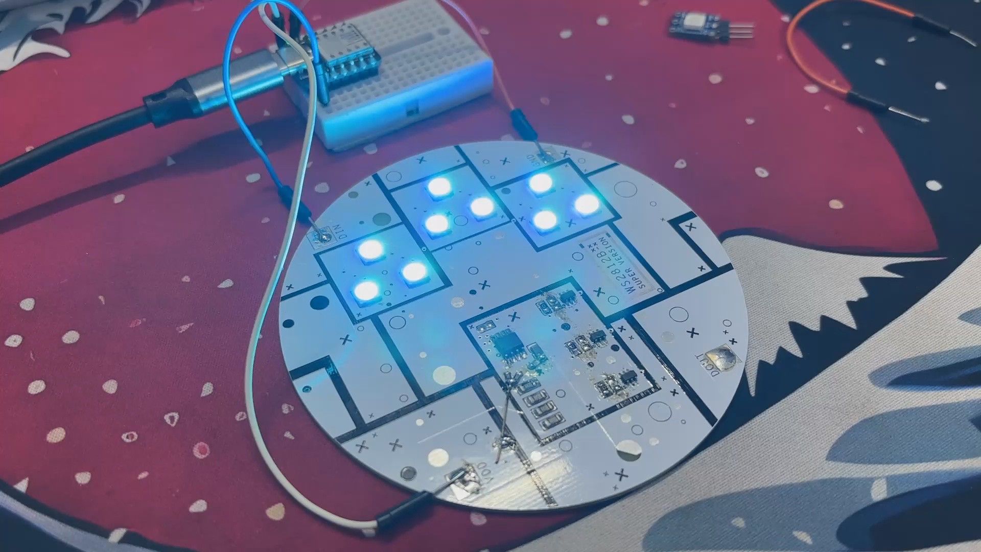
We added a CON1 connector with four pins to access VCC, GND, DIN, and DOUT, giving us complete...
Read more »