mircemk
Most often, these power supplies give a certain voltage at their output. When experimenting with high voltages, we almost always need a variable value of the generated high voltage. There are several ways to achieve this, and in this project I will try to implement and explain all of these ways in one device. Of course, I will try to make the device as simple as possible and at the same time not to use expensive and difficult-to-find components.
Generally, such a device consists of three separate parts:
- An input source of DC voltage (Usually a voltage of 10 to 60 Volts, and the ability to provide a current of 3A or more)
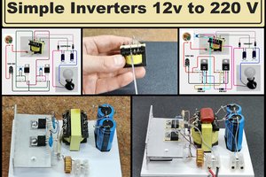
- Then the main part, which is a high voltage generator, or rather a driver for driving a HV transformer - It is a generator of rectangular signals with a certain frequency and duty cycle at the output of which there is a power MOSFET mounted on a large heat sink.
- And a high-voltage (flyback) transformer that generates the high voltage, which can be DC or AC.

Don't miss the PCBWay Christmast Big Sales from November 28th to December 31st. Get free christmas coupons and Redeem or check value a promo code. You ca also start with a PCB Order for Only $5. Up to 50% off for 3D printing & CNC Machining and Special Sales in PCBWay Store! PCBWayhas all the services to create your project at the best price.

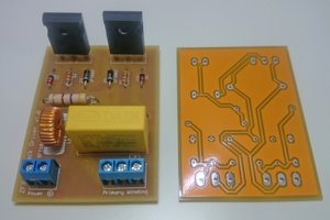
In this project, I will focus most of my attention on making the Driver circuit, which is actually the most complex to make. Let me start by describing the components individually.
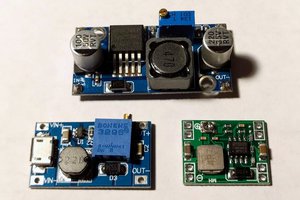
- The heart of the driver circuit is inexpensive Square Wave Generator with adjustable frequency and duty cycle. This incredibly useful - I also call it magical - module is responsible for the stability and versatility of the entire circuit.
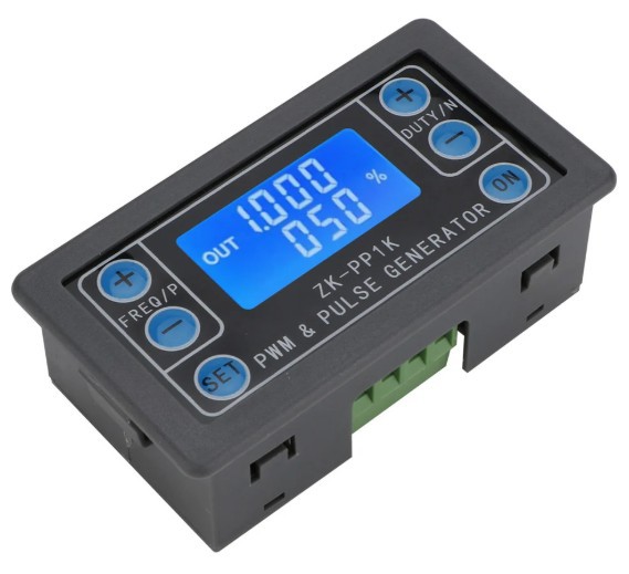
For the price of a few dollars we get a pulse generator with adjustable frequencies from 1Hz to 150kHz, and a duty cycle from 1 to 99%. It even has a small LCD display on which the selected values are displayed. You can notice that I use this module in a number of my previous projects. It can be powered by a voltage from 3 to 30V and the amplitude of the output signal is equal to the supply voltage.
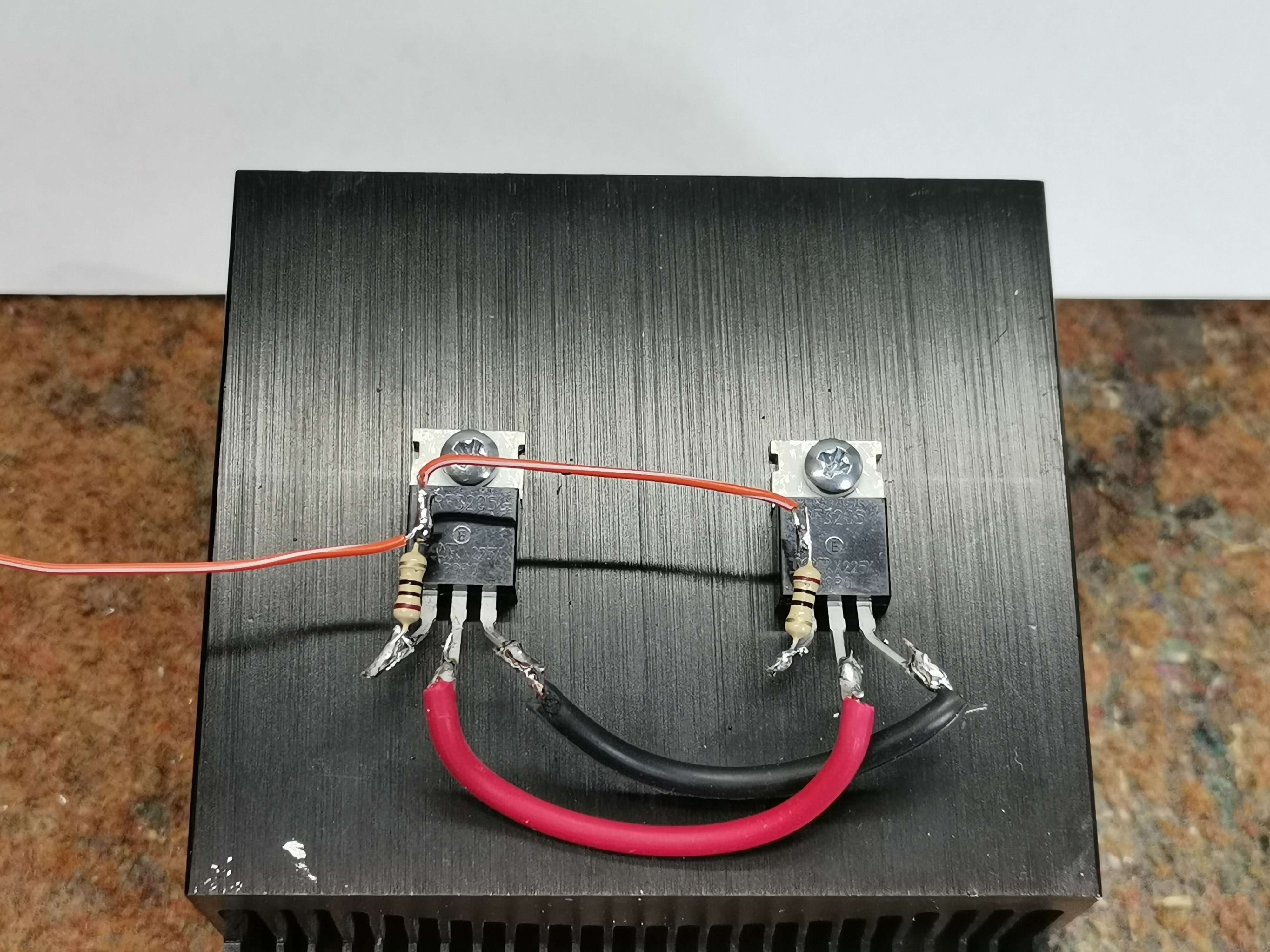
- Then we have two power MOSFETs type IRF3205 connected in parallel amd mounted on a large heatsink that provide power to the low-impedance primary of the HV Transformer.
- 7812 Linear voltage stabilizer which serves to power the ZK-PP1 Module. This stabilizer limits the output rectangular signal to 12V in case we use a power supply greater than 15V, thereby protecting the gate of the output mosfets.
- At the signal output of the generator has a potentiometer with which the amplitude of the generated signal can be continuously regulated.
- At the input side of the low-voltage source, there is an automatic fuse that trips in the event of a driver failure, most likely a burnout of the Mosfets.
- And a few optional components that serve us for better monitoring of the device, which are this small voltammeter at the input, as well as an analog instrument for an approximate representation of the value of the output high voltage.
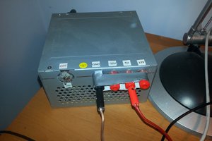
Now let's see how the device works in real conditions. At the input, I initially bring 12V and a current limited to 2A. At the output, I connected a Flyback transformer from an old CRT monitor, on whose core I wound a primary consisting of 7 windings. Here we need to experiment because in different models of transformers the number of windings to achieve the highest efficiency is different. Now we activate the power supply and a spark should appear on the secondary of the transformer. If there is no spark or it is very small, and the current does not exceed 2A (the protection does not turn on), we need to choose a different frequency and duty cycle of the generator. In fact, the duty cycle should be in the range of 30 to 45% and the frequency from 15 to 30 Kilohertz depending on...
 Azri Jamil