Alexander Andrew Antoun
Dear Reader:
This is currently a WIP, and I've yet to finilize a lot, which is why some information is omitted, such as my hardware setup and github links. As such what is currently here may not make complete sense when you are reading this, however I intend to update this section as I go
Software:
Currently to make this project work I am using Mosquitto broker on the same device as the Qt chart, which can then just listen on localhost. If I do decide to make a dedicated server, I think it would be best to just make it another project and keep this micro controller project small in scope
Programming the controller is done with PlatformIO instead of the arduino IDE, no good reason for that, I just like VS Code UI so much more that Arduino IDE.
Hardware:
Two MAX6675 digital converters which handle reading the k-type thermocouples such that the difference of temperature between the hot measuring junction, and the reference junctions are accounted for as well.
To work with those converters I also have 2 K-type thermocouples, one with a stub nose, which is to read ambient temperature when smoking meat, as its such a fundamental part of smoking. The other sensor is of the long pointy form so that I may stab the meat I'm cooking, and measure internal temperature.
Finally the controller is the Arduino MKR1010, and it was chosen because I wanted a small form factor, with low power demands to support sitting outside next to a hot smoker for hours at a time. The MKR1010 provided an out of the box solution to networking needs as well
Current Task
Need to solder project together so that the whole thing is not so flimsy, and the wires can be connected to all cleanly
Arduino Code
I'm not yet ready to share my code publicly as my WiFi credentials are still hard coded, but the overall loop works as below
void loop()
{
  bool somethingToSend = false;

  // if(temperatureSensors.readAmbientTemperature()) TODO: Figure out how to make sensors share same buffer
  // {
  //   somethingToSend = true;
  //   double ambientTemperature = temperatureSensors.getAmbientTemperature();
  //   networkInterface.SendMessageTemperature(ambientTemperature);
  // }

  if(temperatureSensors.readInternalTemperature())
  {
    somethingToSend = true;
    double internalTemperature = temperatureSensors.getInternalTemperature();
    networkInterface.SendMessageTemperature(internalTemperature);
  }

  if(!somethingToSend)
  {
    networkInterface.Poll();
  }

  LowPower.sleep(250);
}
The loop depends on 2 main parts, with an additional LED control which is not super useful to overall project.
- MQTT client class which (as you likely have guessed) sends the temperature data over my home WiFi via MQTT. The broker runs locally on my personal laptop.
- MAX6675 handler, and by extension what actually measures the temperatures. handles the chip selection of SPI and gathers the data.
- the onboard LED just changes color based on the Arduino's connection to the MQTT broker and WiFi - as the device is to run without a computer I figured it would help in making sure all is good. Its omitted from the loop as it doesn't need to change per step. Its only used in the Setup().
Both converters are managed by the one class. This object (I mean the class that manages the sensors) takes a periodic reading, which is organised in two circular buffers type logic - one for ambient, another for internal. Once the buffers are full the main loop receives that there is data to send to the broker, that data is the temperature readings from the buffers. Rather than spam the broker with several "noisy" temperature readings, both sensors buffers are averaged out to reduce "noise", and those value is determined to be the current temperatures. Data is sent every second.
One thing about selecting the sensors with the MKR1010 is that the board has internal pullup resistors, so when using the MAX6675's read function, I need to make the pin an output pin with Arduino.h pinMode() function. After the reading, I also set the pin to be an input with Pullup enabled. These steps is how the chipselect can be "pulled low".
Below is the ambient temperature read logic, the internal temperature read logic is identical except the CS pin is different
bool ThermocoupleInterface::readAmbientTemperature()
{
    bool readyToReportTemp = false;

    pinMode(AMBIENT_CS_PIN, OUTPUT); //read Celsius assumes given pin is wired to external pullup
    // so need to explicitly set pin to output mode

    ambientTemperatureBuffer[bufferIndex] = static_cast<double>(ambientThermocouple.readCelsius());
    pinMode(AMBIENT_CS_PIN, INPUT_PULLUP);

    ++bufferIndex;

    if(BUFFER_SIZE == bufferIndex)
    {
        bufferIndex = 0;
        readyToReportTemp = true;
    }

    return readyToReportTemp;
}
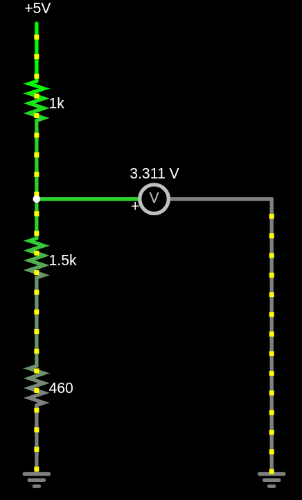
Adding Tri-State Buffer
To be able to make the MISO pins of the two MAX6675's share the same pin, I used the SN74AHCT125N integrated circuit chip. The output enable pins of this IC are active-low, which makes is very convenient for the chip select of SPI protocol, as you need to pull that line low to enable the peripheral device. This IC outputs at 5V though so a voltage divider circuit is required for the MKR1010, can only take 3.3V safely. In my voltage divider circuit used a 1k ohm resistor as the first voltage drop source, then output to MKR1010, then 2 resistors in series that sum to 1.9k ohms. See below circuit diagram from falstad sim: