 JP Gleyzes
DJI Motion Controller
The DJI motion controller 1 was provided by DJI when I bought the drone pack.
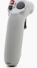
This device is very cool and allows to pilot the drone even though you have never flown a drone... It's sooo simple !
I wanted to reuse this device to try to pilot RC planes connected to my TX16s buddy box.
It's easy to connect to motion controller to a PC or a smartphone and see it as a joystick.
But its outputs are quite misleading... So I decided to spend some time on this tricky challenge !
Decoding the Motion Controller
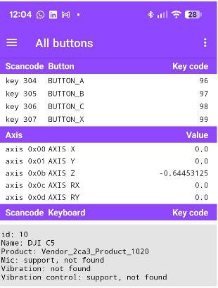
I mounted the device on a tripod and connected it to my phone with a USB cable and entered the data into my phone using gamepad Tester App
It told me that this device has 4 buttons and 5 axis
- X, Y and Rx are interresting rotations (yaw, pitch roll... almost !) (values -1 to +1)
- Z is throttle (values -0.64 to + 0.64)
- Ry is the gimbal motion (values -0.64, 0 and +0.64 three positions switch)
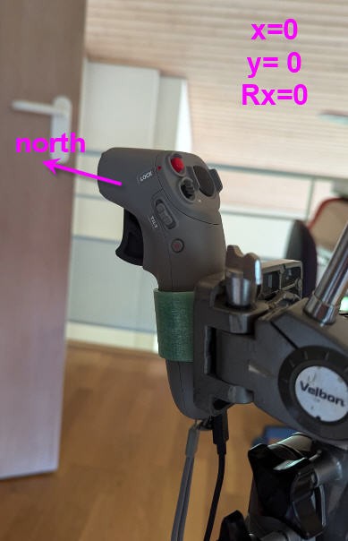
If I align the motion controller to the north values are
- x = 0
- Y = 0
- Rx = 0
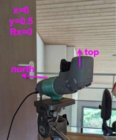
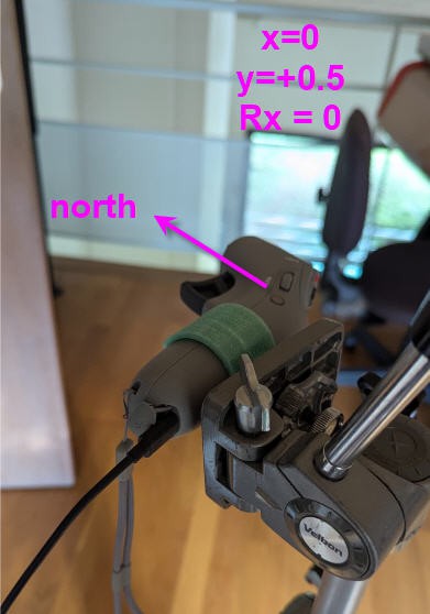
from this "zero" postion if I rotate one axis to point to top I get
- x = 0
- y = 0.5
- Rx = 0
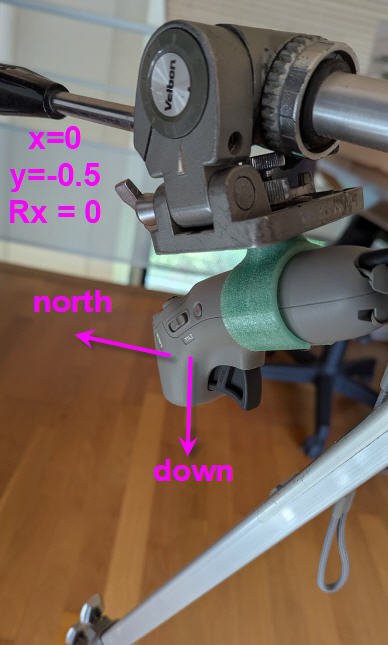
if I continue rotation on the same axis, pointing to north and down, I get:
- x =0
- y= -0.5
- Rx = 0
if I rotate around the vertical axis from "zero" postion to point to "east" I get:
- X = 0
- Y = 0
- Rx = 0.5
if I go on to point to south I get
- X = 0
- Y = 0
- Rx = 1 (and if I go a little further to south west it jumps to -1)
now if I start from "zero" position and twist on the "roll" axis 90° I get
x=0
y= 0.5
Rx = 0
Preliminary conclusions
The yaw axis is directly given by Rx value. It's an angle in the fixed reference frame of earth (values -1 to +1 for -PI to PI)
X and Y axis are given also in the earth reference frame (so they move together when you rotate around the vertical axis).
If we want them in motion controller ref frame (as any joystick or RC controller) then we have to apply rotation transformations from this fixed frame to the moving one (your hand)
Finally Rx gives an absolute angle. We want an angular velocity to control the rudder of our plane. So we need to evaluate the variation of Rx angle during time...
fixed frame to hand frame
Heading angle
heading = Rx * pi (expressed in radians, absolute value 0 = North)
Pitch angle
Pitch= -( Y*cos(heading) - X*sin(heading))
Roll angle
{Roll= - ( X*cos(heading) + Y*sin(heading))
With these formulae we have pitch and roll expressed into your "hand" ref frame. But heading is still espressed as an absolute value relative to north... To convert heading into yaw motion we need "a trick"
I used the "gimbal rotation" axis to latch the current heading (position of your hand relative to north) and then to compute variation of heading from this position.
If I release the gimbal switch then yaw is reset to zero until you press again this button.
I did try other solutions (introducing a "dead band" closed to yaw = 0 and detecting motion only if at a certain speed. It worked but was prone to some confusion.... So this simple "press and yaw" solution seemed to be better !
Test application
I wrote a small Basic for Android Application, starting from a working gamepad decoder, and implementing the formulae above.
result can be seen into this video
Current status is that it is quite easy to decode this motion controller and to compute "classical" Yaw/Pitch/Roll values that we could into into our RC radio Rudder/Elevator/Ailerons.
So next step will be to try to embed this code into a ESP32-S3 MCU to connect all this to my Buddy box