 Paul
PaulOnce this works, you can treat TinyTTS as a small “speech layer” you can drop into any future Arduino project whenever you need voice feedback instead of (or in addition to) LEDs and displays.
Project Overview
We’ll use the same basic wiring in two modes:
- Scenario 1 – USB demo
PC → Arduino (USB Serial) → TinyTTS (UART).
You send text from a terminal on your computer, TinyTTS speaks it.
- Scenario 2 – Sensor‑driven
Sensor → Arduino → TinyTTS.
Arduino reads a sensor (temperature in the example), builds a string such as "Temperature is 23 degrees," and sends it to TinyTTS.

The only real difference between the scenarios is where the text comes from.
The TinyTTS interface stays identical in both cases.
How It Works
TinyTTS behaves like a simple UART device:
- It listens on RX for lines of text.
- When it receives a line ending with newline (\n), it converts that text to speech and plays it on the audio output.
On the Arduino side:
- PC interface: Used for debugging and receiving text input from the computer.
- TinyTTS interface: Used to send the text to the module.
For Arduino Mega: This board has multiple Hardware Serial ports. You can use the standard USB connection for the PC and a second Hardware Serial (e.g., Serial1 or Serial 2) to talk to TinyTTS reliably at high speeds.
For Arduino Uno/Nano: These boards have only one Hardware Serial (Pins 0 and 1). To ensure reliable audio performance, we connect TinyTTS to the Hardware Serial. To communicate with the PC simultaneously, we use aseparate USB-TTL adapter connected via SoftwareSerial on digital pins.
In code, this boils down to just one operation:
if (debugSerial.available()) {
// 1. Read plain text from the PC via the USB-TTL adapter
// ... read into inputBuffer ...
// 2. Convert to TTS protocol and send to module via Hardware Serial
speak(inputBuffer);
}
In Scenario 1, you call speak() with text from the PC.
In Scenario 2 you call speak() with text built from sensor readings.
Hardware
You can reproduce this project with common Arduino parts.
Core components
- TinyTTS module
– UART interface for text input
– 3.5 mm audio jack for headphones or speaker
- Arduino‑compatible board
Tested with:
– Arduino Uno
– Arduino Nano
– Arduino Mega 2560
Any board that has a hardware Serial for TinyTTS and a second serial port (hardware or software) for USB will work.
- Speaker or headphones
Plugged into TinyTTS 3.5 mm output.
- USB TTL adapter
To program the board and, in Scenario 1, to send text from a PC.
Sensor for Scenario 2 (example)
- BME680 sensor
You can replace it with another sensor you know well (DHT11/DHT22, photoresistor, HC‑SR04, soil moisture, etc.). The TinyTTS part does not depend on the sensor type.
Wiring
Common Connections (TinyTTS ↔ Arduino)
The basic connections are the same for both scenarios:
- TinyTTS VCC → Arduino 5 V (check your module’s voltage rating)
- TinyTTS GND → Arduino GND
- TinyTTS RX → Arduino TX (Hardware Serial) pin of the serial port you use for TinyTTS
- TinyTTS TX → Arduino RX (Hardware Serial)
- TinyTTS audio jack → speaker or headphones
On Arduino Mega you can, for example, use Serial1:
- TinyTTS RX → Arduino pin 18 (TX1)
- TinyTTS TX → Arduino pin 19 (RX1)
On Uno/Nano you can use Hardware Serial:
- TinyTTS RX → Arduino pin 1 (TX)
- TinyTTS TX → Arduino pin 0 (RX)
Specific Wiring for Arduino Uno/Nano:
Because pins 0 and 1 are used by the TinyTTS module, you must add a USB TTL adapter to send text from your computer.
Additional Sensor Wiring (Scenario 2)
BME680 sensor (Temperature, Humidity, Pressure, Gas):
- BME680 VCC → Arduino 5 V
- BME680 GND → Arduino GND
- BME680 SCL→ Arduino analog input (e.g. A5)
- BME680 SDA → Arduino analog input (e.g. A4)
If you use a different sensor, connect it as recommended in its own documentation. The TinyTTS part of the wiring remains unchanged.
Code Overview and Upload
Scenario 1 – USB Demo: Type Text, Hear Speech
In this scenario, Arduino...
Read more »
 Jerry Isdale
 CanHobby.ca
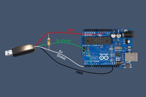
 Doctor Volt
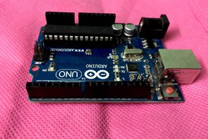
 ensafatef