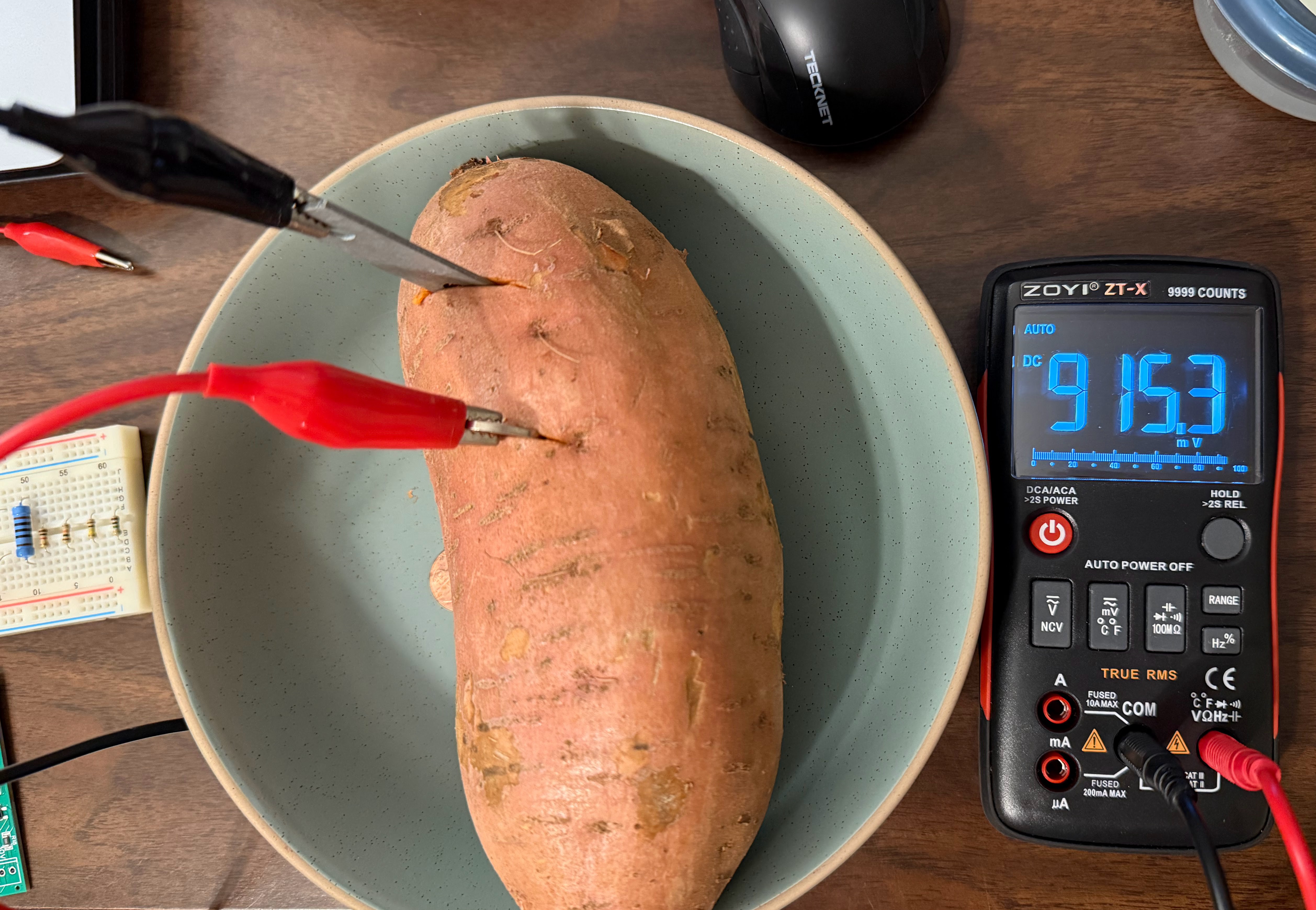
After the initial tests using saltwater and salty vinegar with pennies and nickels were promising but not enough power, I moved on to testing with a sweet potato and zinc electrodes (zinc plated plate, screws, and nails). The first test is shown below. With a nickel and a zinc plate, I was able to achieve a cell open circuit voltage of 915mV, much higher than the prior cells. With a zinc plated nail, it was even higher, at 1.01V! This was very promising that I would be able to use this setup to power the Nanosleeper.
To prepare for testing, I modified the Nanosleeper firmware to sleep more and be in awake mode less. However, I still wanted it to wake reasonably often to flash its LEDs, so I can tell what's happening. Testing the Nanosleeper firmware with MetaShunt, I determined the average current was now 125uA. So, when we give it a 2.1V supply, it takes an average of 263uW to run. The boost converter takes about 55uA at 0.5V, so another 28uW, leading to a total of 291uW. It could certainly be lower with different boost converters (such as the TPS61098, which takes 300nA and can boost down to 0.7V), I'm doing this testing with what I have on hand!
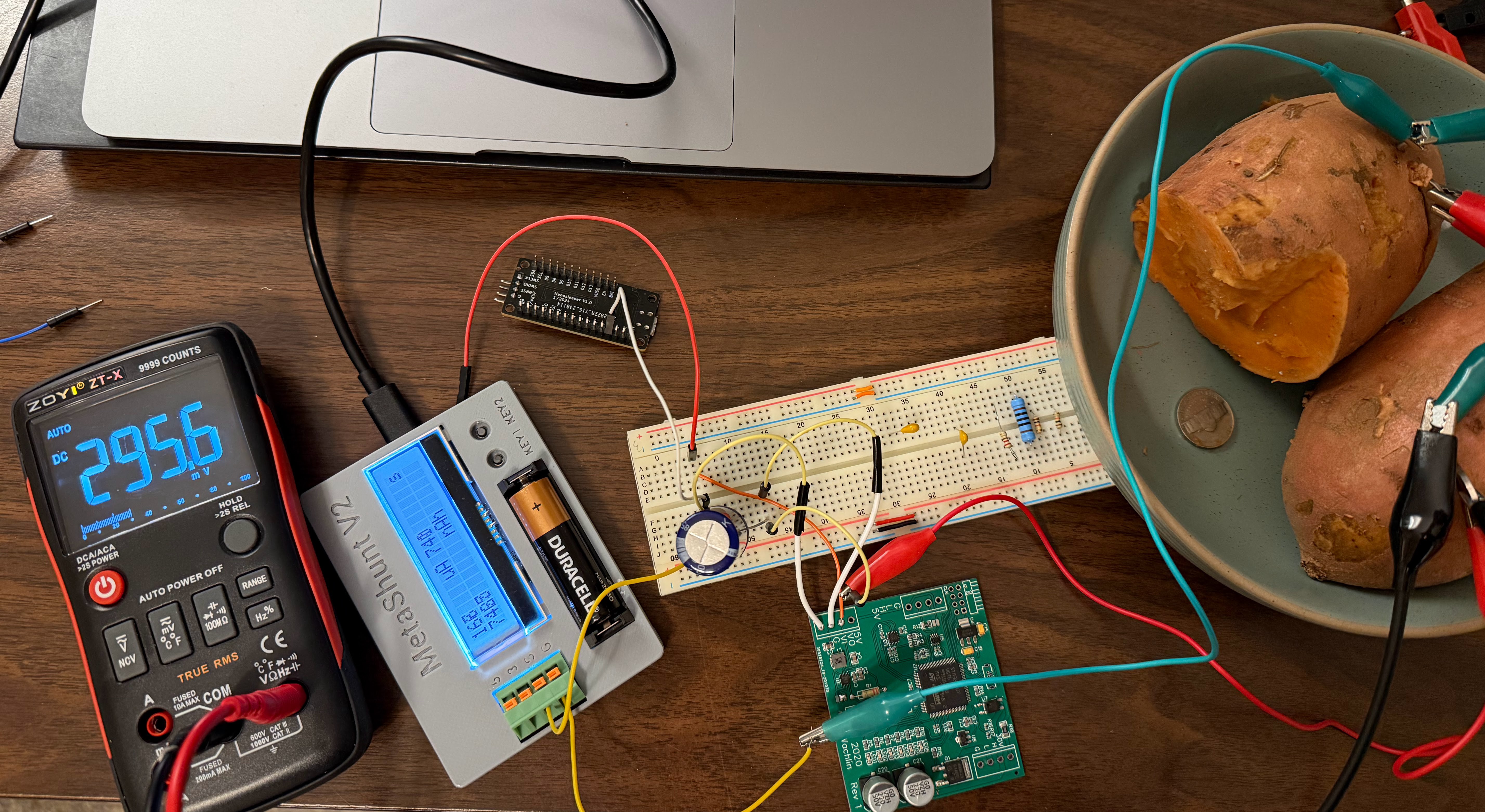
OK, now I set up a series battery with two chunks of potato, 2 nickels, and 2 zinc-plated nails. I was able to use this to charge up a 3300uF capacitor up to 1.6V. I then connected the TPS61200 board, but not the Nanosleeper to the 2.1V rail. I confirmed the 2.1V rail is generated temporarily, but eventually the capacitor drains down and the system settles into the current and voltage shown below (296mV at 168uA). At this voltage, nothing works, but it does provide some insight into the IV curve. At 296mV, this battery provides 50uW, far from the 291uW needed. I probably need bigger electrodes to be able to provide more current.
Discussions
Become a Hackaday.io Member
Create an account to leave a comment. Already have an account? Log In.