 DIY GUY Chris
What you'll get by the end:
- ✅ A fully functional MPPT solar charger
- ✅ Custom PCB that you designed yourself
- ✅ 3D-printed professional enclosure
- ✅ Understanding of battery charging fundamentals
- ✅ All skills to modify and scale the design
No prior PCB design experience? No problem! I'll walk you through every step, from schematic capture in Altium to SMD assembly with a hotplate. Let's harness some sunshine! ☀️🔋
Supplies
Core Electronics Components
These are the essential parts for the circuit. You can source them from distributors like LCSC, Mouser, or Digi-Key.
LT3652 IC (1 piece) - PowerDFN-12 or MSOP-12 package. This is the brain of the charger, handling MPPT and battery charging control.
Inductor (1 piece) - 10µH, with at least 500mA saturation current (like MAPM0630F-100M-LF). This stores and transfers energy in the buck converter circuit.
Schottky Diode (1 piece) - 1N5819 (1A, 40V). Prevents reverse current from flowing back into the circuit.
Current Sense Resistor (1 piece) - 0.4Ω, 1/4W rating. Sets the maximum charge current to about 250mA.
LEDs (2 pieces) - One red (for CHRG) and one green (for FAULT), 0805 size. These show the charging status.
JST-PH Connector (1 piece) - 2-pin type (like S2B-PH-K-S). For connecting your Li-Ion battery.
Resistors & Capacitors - Various 0603 or 0805 package components as shown in the schematic. These handle configuration, filtering, and voltage dividing.
Potentiometer (1 piece, optional) - 10kΩ, through-hole. Allows you to adjust the MPPT voltage if needed.
📄 Full Bill of Materials (BOM): For a complete, clickable list with exact values and suggested part numbers, check the project's GitHub repository (link in the final step).
Tools & Equipment
Soldering Setup: Either a fine-tip soldering iron OR a hotplate/reflow oven for SMD work.
Solder Paste & Stencil: For reflow assembly (JLCPCB provides this when you order).
Precision Tweezers: Essential for handling small SMD components.
Multimeter: Crucial for testing and debugging your circuit.
Magnifying Glass or Microscope: Very helpful for inspecting tiny solder joints.
Fabrication & External Services
PCB Manufacturer: I used JLCPCB for fast, affordable boards.
3D Printing Service: For the enclosure. I used Prusa, but any service or your own printer works.
Solar Panel: 12V, 250mA (any panel in the 6V-18V range will work).
Battery: 3.7V Li-Ion/LiPo with a standard JST-PH connector.
Optional but Helpful
Bench Power Supply: Useful for testing without the solar panel.
USB-to-Serial Adapter: If you decide to add monitoring features later.
Double-sided Tape or Adhesive: For mounting components inside the enclosure.
Pro Tip: Order a few extra of the smallest components (like the 0603 resistors and capacitors) – they're cheap and easy to lose!
Next Step: Let's look at the circuit schematic and understand how all these parts work together.
Schematic & PCB Design
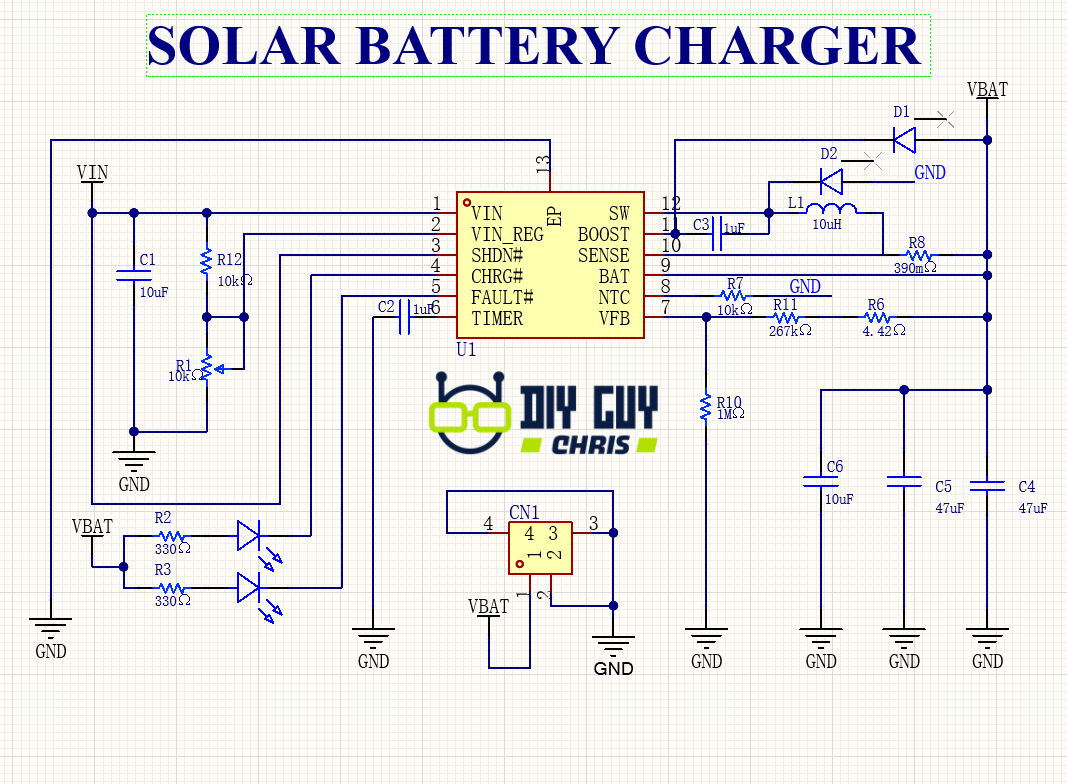
We start by creating the circuit blueprint. Using Altium Develop, I translated the LT3652's requirements into a functional schematic. The design centers on two critical voltage dividers: one on the VIN_REG pin to set the MPPT voltage (~14.4V for a 12V panel), and another on the FB pin to set the battery float voltage (~4.2V). The JST battery connector, status LEDs, and all passive components were placed to ensure a clean power flow and easy assembly.
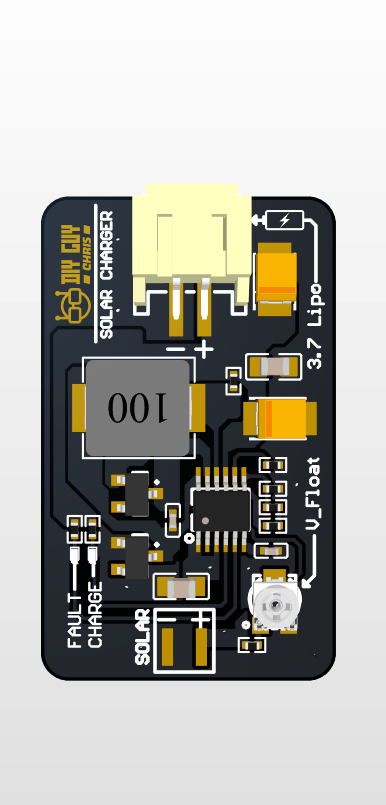
The PCB layout prioritizes a clean power path. The power traces from the solar input, through the LT3652, inductor, and to the battery are kept short and wide to minimize loss. The sensitive feedback networks for VIN_REG and FB are placed close to the IC to avoid noise. The final board measures a compact 35mm x 25mm. Before sending it off, the 3D model view is crucial for a final check, ensuring no components collide and the connectors are accessible.
Assembly (SMD Soldering)

With the PCBs and stencil in hand from JLCPCB, assembly begins. After aligning the stainless steel stencil perfectly over the board, I spread a thin, even layer of solder paste across all pads using a squeegee. The key to successful pick-and-place is good lighting and steady hands with precision tweezers. Pay special attention to the orientation of the LT3652 IC (match the dot on the chip with the dot on the PCB silkscreen) and the polarity of the diodes and LEDs.

The magic happens during reflow. Using a controlled hotplate, I gently heat the board. You watch as the solder paste first dries, then melts into shiny, silver joints, a process called "reflow." Once it cools, a thorough inspection under magnification checks for solder bridges or poor connections, followed by a cleaning with isopropyl alcohol to remove flux residue.

3D Printed Enclosure

To turn the PCB into a robust, portable unit, I designed a custom enclosure in Solidworks. The design has precise cutouts for the solar panel, Battery and charging circuit. I exported the model as an STL file and 3D printed it using matte black PLA filament for a clean, professional look.

After printing, I test-fitted the PCB and solar panel. A small amount of double-sided tape securely mounts the solar panel to the top of the case, while the PCB snaps neatly into the posts.
Testing & Final Results

Time for the moment of truth. First, a visual and continuity check with a multimeter ensures there are no short circuits. For the initial "smoke test," I connect only the 12V solar panel (or a lab power supply). The circuit should power on, with the FAULT LED possibly blinking to indicate no battery—this is normal.
Next, I connect a discharged 3.7V Li-Ion battery. The red CHRG LED turns on solid, confirming the charging cycle has started. A quick measurement shows the solar input is being regulated to the MPPT setpoint (~14.4V), not sagging down to the battery voltage. As the battery approaches the full voltage set by the FB divider, the charge current tapers. Finally, the CHRG LED turns off, signaling termination. The system automatically restarts charging if the battery voltage drops by 2.5%. Success! You now have a fully functional, efficient solar charging station.
🙏 Acknowledgments
- Analog Devices for the excellent LT3652 IC and documentation
- JLCPCB for reliable PCB fabrication services
- Altium for providing professional PCB design tools
- Open Source Community for continuous inspiration and support