 Sagar 001
Current sensing is very important as an electronics engineer for me, It made me think to grasp the topics of OPAMPs with a better approach. When I used to design my circuit in the past, I did not even look at the amplifier specs, just put a resistor and measure the voltage across it. Then amplifying it a bit and measuring with ADC. This method works well but introduces non linearity noise and errors. That's what I think is why my measured value drifts over voltage. The issue is I am using the minimal yet working setup because it is easy to do. And if you don’t care too much about accuracy of a few mA then this method is good to go. But with some optimal approach and adding a few more components increase the accuracy and reduce the overall noise.
In many of my battery-powered designs, I needed a simple and easy to measure current sensor without disturbing the system. In low-power systems, current variations are often subtle but critical:
- A microcontroller in sleep may draw a few microamps
- A sensor waking up may draw milliamps for milliseconds
- A battery charger may behave correctly in voltage but fail in current regulation
That requirement led me to design a compact high-side current sensing board using the CSA220 current-sense amplifier.
Using Current Sense Resistors:
Current itself is not measured directly. Instead, we convert it into a voltage using a current-sense resistor (shunt).
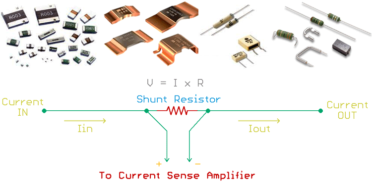
V_sense = I * R_sense
So if we are using a shunt resistor of 10 mΩ, then:
- At 1 A, sense voltage = 10 mV
- At 100 mA, sense voltage = 1 mV
These voltages are too small to measure directly with a multimeter or MCU ADC. That’s where the CSA220 comes in.
Why Not Use a Simple Op-Amp?
At first glance, it might seem tempting to amplify the shunt voltage using a regular op-amp. The limitations are in the internal circuits of OPAMPs.
Input Common-Mode Range: Every operational amplifier has an input common-mode range (ICMR), if the input voltage meets the ICMR range it works perfectly but produces non-linearities beyond that. Hence if a 5V opamp has ICMR of (0 to 3.5V) we can not apply a signal greater than 3.5 at the differential input.
Poor CMRR at High Voltage: Small sense voltages (µV–mV) riding on large common-mode voltages require extremely high common-mode rejection. It is basically how well the two signals cancel out if they are the same, defined for a range of voltages again!
Offset Voltage Dominance: When there is no signal or short condition then the input offset voltage due to the internal transistor mismatch in the opamp may create a voltage at output. When measuring 1–10 mV, even a few microvolts of offset introduces large errors.
Using Current Sense Amplifiers - CSA220
The CSA220 is a dedicated high-side current-sense amplifier, designed specifically for this task. And because of special internal architecture they have:
- Input common-mode range: 0 V to 76 V
- Low input offset voltage: typically 5 µV
- High CMRR: up to 157 dB
- Fixed, precision gain (10 V/V in my case)
These specs allow accurate measurement of millivolt-level signals even when the shunt is sitting at high voltage. We will discuss the basics of high side and low side current sensing in the end, but here is my minimal design of CSA 220.
Components Required:
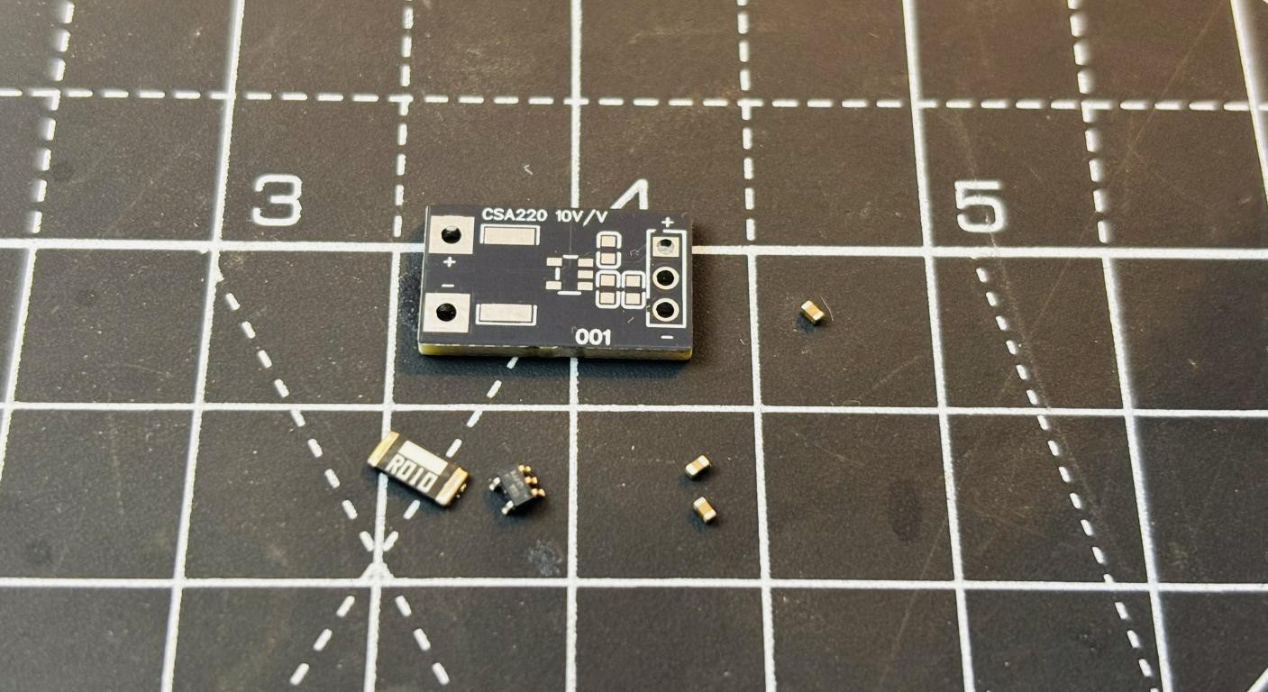
- CSA220
- 10 mΩ precision shunt resistor
- 100nF ceramic capacitor
- Pin headers
- 3V Power source
- Multimeter (basic)
Circuit Diagram and Schematics:
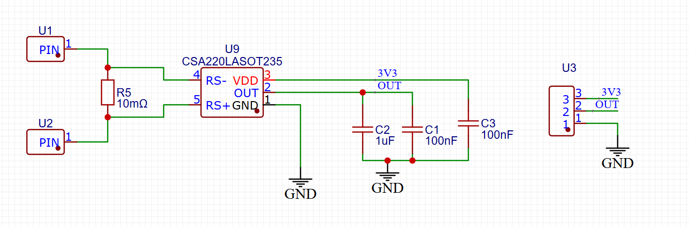
The circuit is very simple and uses minimal external components. I am using a 10 mΩ precision shunt resistor. The resistor chosen should be precise enough to 1% tolerance. CSA220-10, 10 V/V gain version is used in the schematics, to keep my multimeter calculations straight forward. Current is just a decimal forward form the output voltage. The output headers are placed on the other side, so we can plug it into any board and do the measurements. I have placed some decaps, I do want to follow the PSRR regulation profile but not required here. The output voltage will be:
V_out = I * R_sense * GAIN
PCB Layout:
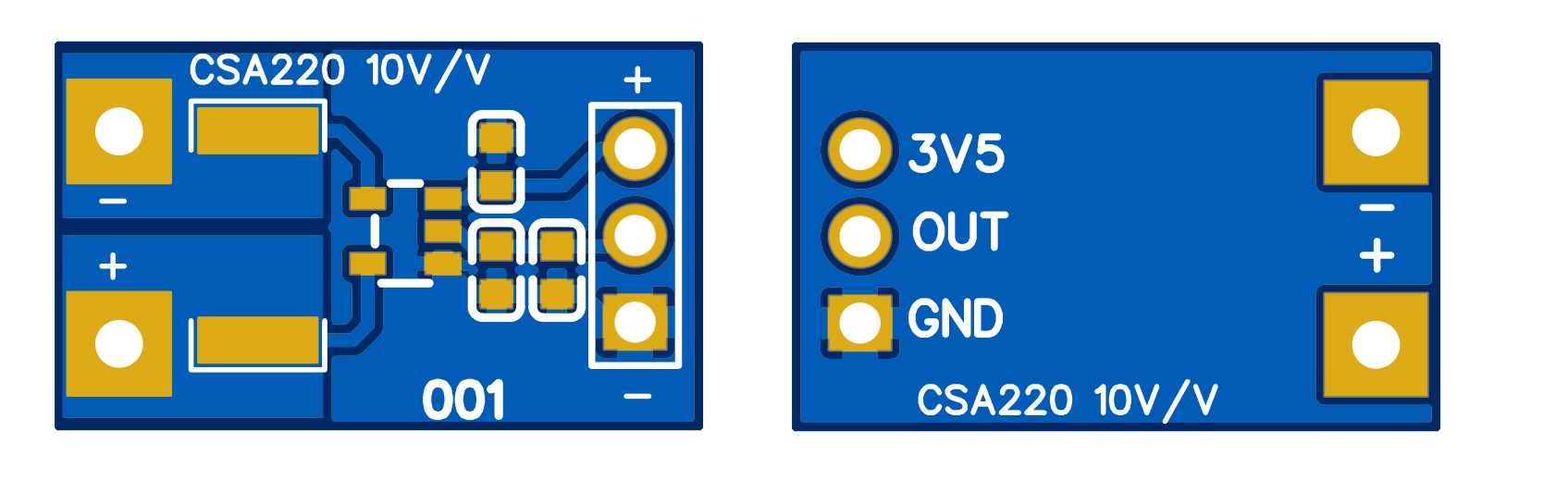
I am using the polygon plane method because it is a small PCB. If you want to know kelvin wire measurement, draw small traces from current sense resistor to amplifier. It will reduce the overall parasitics and maintain the power integrity as it is. High-current paths are kept short and wide, analog output trace is isolated from switching currents hence the header is placed on the other side. The decoupling capacitor is placed close to the VDD pin. Download the required files from here.
Taking the Project to the Next Level - With JUSTWAY
Electronics without proper housing and the audio circuit, they simply would not work. Yes! Because to keep the system available to us a proper 3D casing should be there. JUSTWAY assists you in turning your do it yourself project into a high-quality prototype that feels and looks like a genuine product that is ready for the market. What they do:

- Rapid Prototyping
- CNC Machining (Aluminum 6061 / Stainless Steel 304)
- Sheet Metal Fabrication
- Injection Molding
- Urethane Casting
- 3D Printing (SLA & HPA-PA12)
Upload your CAD files at JUSTWAY.com, Select the material & finish then preview your model in 3D and place your order.
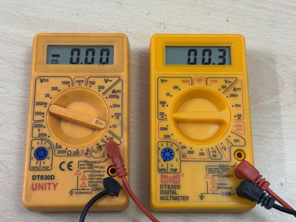
Measurement on a Multimeter:
As per the calculations:
- 1 A → 10 mΩ × 10 V/V = 100 mV
- 2 A → 200 mV
- 5 A → 500 mV

Because this CSA220 works well at a 3V supply hence I want to power it with a 3V single coin cell. Because I have limited voltage headroom available and I do not want to put more amplifiers. That’s why I have chosen the multimeter method. My simple low cost multimeter can measure 1mV (10mA resolution) minimum then why use a special ADC, if my aim is to just interpret the current. By the way, I have made it as a breakout for a purpose such that I can integrate with any MCU in future. I am currently working on a power analyzer in which I require the same but a little optimized and low noise current sensing. By varying the different resistors I can do that in future. For now this current meter can easily sense the current up to 10A and give very accurate results. I simply connect my voltmeter across the OUT pin, and the current is now visible as a clean analog voltage. So that’s how I can see the current consumed by any device by interpreting the waveforms through a scope.
Deciding between High/Low-Side Current Sensing:
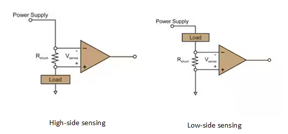
Low-Side Current Sensing:
The shunt resistor is placed between load and ground. Now the ground potential we are using is not the same as actual ground, the actual ground is below the newly created ground reference; this is called ground shifting. This will break ADC references and communication grounds. Which is not a good method, yet very easy. One major drawback is that because the actual ground is below the created reference, the small voltage developed across the sense resistor can exceed the negative limit of ICMR which may create problems in measuring high currents.
High-Side Current Sensing:
In this method the shunt placed between supply and load, the ground remains intact. It is slightly more complex and then we have to see the upper range of ICMR. It should be more than enough to do this. If using the general purpose amplifiers they can not perform this operation. So either go for a special current sensing amplifier or for a rail to rail opamp.